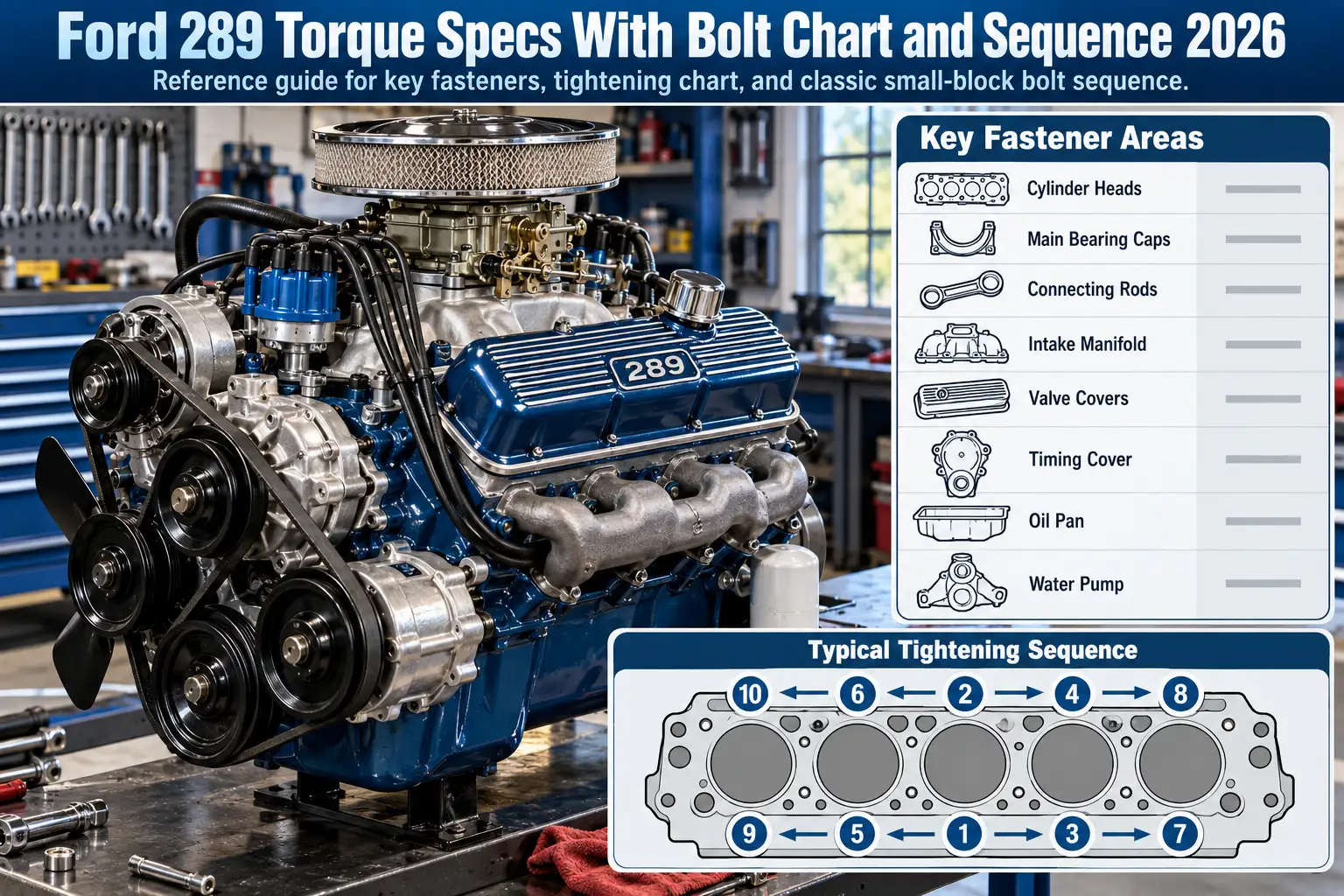
Ford 289 Torque Specs With Bolt Chart and Sequence 2026

Ford 289 torque specs depend on the fastener and engine configuration. For a factory-style 1966 289 V8, cylinder-head bolts tighten in three passes at 50, 60, and 65–70 ft-lb. Main bearing caps use 60–70 ft-lb, while standard connecting-rod nuts use 19–24 ft-lb.
Those figures are not interchangeable with 289 High Performance rod hardware or aftermarket bolts and cylinder heads. The chart below separates factory fasteners from those exceptions and explains how to follow the head and intake tightening sequences.
Ford 289 Torque Specs Chart for Stock Engines
Recommended Best Deal Products
The following figures are drawn primarily from the 1966 Ford Comet, Falcon, Fairlane and Mustang shop manual and its 289 V8 torque-limit tables. They are reference specifications for the stated factory hardware, not a substitute for the manual matching your specific year, parts and fastener condition.
| Component | Torque in ft-lb | Torque in N·m | Application and notes |
|---|---|---|---|
| Cylinder-head bolts | 50, then 60, then 65–70 | 68, then 81, then 88–95 | Factory-style 1966 iron-head installation; use the specified sequence |
| Main bearing-cap bolts | 60–70 | 81–95 | Factory two-bolt main caps |
| Connecting-rod nuts, standard 289 | 19–24 | 26–33 | Standard production rod hardware |
| Connecting-rod nuts, 289 HiPo | 40–45 | 54–61 | 1966 manual’s High Performance application; verify installed rods and year |
| Intake-manifold bolts | 15–17, then 20–22 | 20–23, then 27–30 | 1966 factory manifold procedure; use the intake sequence |
| Exhaust-manifold bolts | 13–18 | 18–24 | 1966 factory reference |
| Flywheel-to-crankshaft bolts | 75–85 | 102–115 | Factory flywheel hardware |
| Vibration-damper retaining bolt | 70–90 | 95–122 | Crankshaft damper fastener |
| Oil-pump-to-block bolts | 23–28 | 31–38 | Factory oil-pump mounting |
| Water-pump bolts | 12–15 | 16–20 | Factory mounting arrangement |
| Engine front-cover bolts | 12–15 | 16–20 | Factory front-cover hardware |
| Valve-cover bolts | 3–5 | 4–7 | Light gasket clamping only |
| Oil-pan bolts, 1/4-inch | 7–9 | 9–12 | Identify bolt diameter before tightening |
| Oil-pan bolts, 5/16-inch | 9–11 | 12–15 | Do not apply the same setting to both bolt sizes |
Conversion note: Metric values are rounded from 1 ft-lb = 1.35582 N·m. Preserve the specified ft-lb range rather than interpreting a rounded N·m conversion as a more precise requirement.
The chart deliberately distinguishes 1966 factory specifications from later Windsor and modified-engine practices. An engine assembled with replacement rods, head studs, a different intake, or a non-original block may need a different specification. In particular, engine-output torque in lb-ft is not the same measurement as fastener tightening torque, even though both use torque units.
Which Ford 289 Version Changes Bolt Torque
The 289 belongs to Ford’s small-block Windsor family, but displacement alone does not identify every installed fastener. Before building an engine, check its production year, casting details and actual components. Our Ford engine sizes chart helps distinguish the 289 from related Windsor engines, including the 302.
Standard 289 V8 Engines
The regular two-barrel and four-barrel 289 applications generally use the standard production connecting-rod fastener specification shown above. For the documented 1966 hardware, that means 19–24 ft-lb at the rod nuts and 60–70 ft-lb at the main caps.
Do not identify a rebuilt engine solely by its car’s VIN or air-cleaner decal. A previous owner may have installed different rods, a replacement short block, or new fasteners. The hardware on the workbench determines which tightening instructions apply.
High Performance K-Code 289 Engines
The 271-horsepower High Performance 289, commonly called the HiPo or K-code engine, uses distinctive connecting rods and heavier-duty rod hardware. The 1966 service table assigns its rod nuts 40–45 ft-lb, not the standard 19–24 ft-lb range. Other reproduced historical references give a slightly wider upper limit, so the year-specific manual is the deciding authority.
Our 1965 Ford Mustang K-code guide covers the engine’s identification context. Treat the code as a starting point, then confirm the actual rod bolts before applying torque.
How to Tighten Ford 289 Cylinder Head Bolts
Recommended Best Deal Products


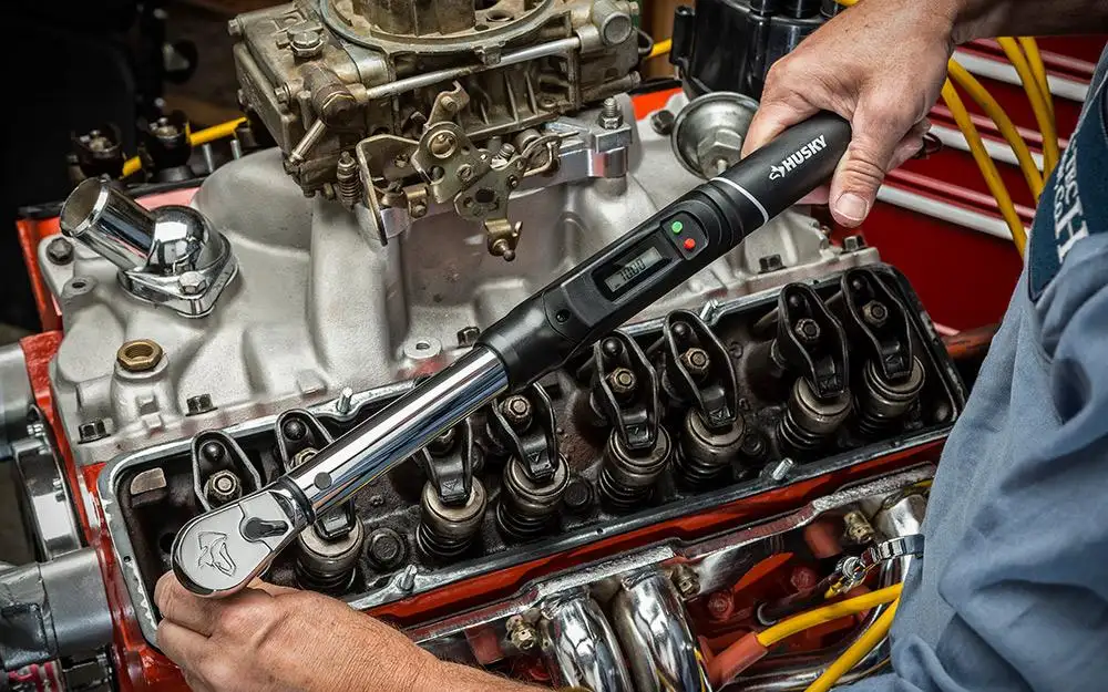
For a factory-style 1966 Ford 289 with the appropriate iron heads and original-type head bolts, the service procedure calls for three complete tightening passes. Do not tighten each bolt straight to final torque before moving to the next one.
Ford 289 Head Bolt Tightening Stages
| Pass | Torque in ft-lb | Torque in N·m |
|---|---|---|
| First | 50 | 68 |
| Second | 60 | 81 |
| Final | 65–70 | 88–95 |
Each cylinder head has 10 head bolts. The conventional small-block Ford tightening order starts near the center and works outward. The layout below is a top-view sequence aid, with the front of the engine on the right; match bolt positions against the head diagram in the manual for your application.
REAR                                  FRONT →

Upper bolt row:     9     5     1     3     7
Lower bolt row:    10     6     2     4     8
The numbers identify the order, not the cylinder numbers. On each pass, follow positions 1 through 10 before advancing to the next torque setting.
Cylinder Head Installation Steps
- Confirm the parts. Verify that the heads, gasket, bolts and washers match the 1966 factory-style configuration. Check the bolt lengths and hole depths.
- Prepare the bolt holes. Clean out old sealer, oil and debris without damaging the threads. Use the thread sealant or lubricant specified for your exact hardware; the period Ford service procedure calls for water-resistant sealer on applicable head-bolt threads.
- Seat the head and gasket. Confirm the gasket orientation and dowel alignment. Thread every bolt in by hand to ensure it engages cleanly.
- Complete the first pass. Tighten every bolt in the numbered sequence to 50 ft-lb.
- Repeat the entire sequence. Bring all 10 bolts to 60 ft-lb, then complete the final pass within 65–70 ft-lb according to the applicable manual.
- Finish to the specified procedure. Follow the gasket or fastener maker’s retorque instructions, if any. Do not loosen and retighten completed bolts without a procedure that calls for it.
This sequence and these stages are not a blanket instruction for later 302 heads, head studs, or replacement aluminum heads.
How to Tighten Ford 289 Intake Manifold Bolts
The factory intake manifold has its own tightening pattern. The 1966 shop manual lists a 15–17 ft-lb initial stage followed by 20–22 ft-lb for its factory intake arrangement. The bolts must be tightened in the intake’s specified center-out sequence, not merely from left to right.
Factory Cast Iron Intake
Start with the manifold and gaskets positioned correctly and all 12 mounting bolts engaged by hand. Work progressively through the numbered factory intake sequence, completing the lower-torque pass before applying the final setting. Confirm that the manifold seats evenly against both cylinder heads and that the end seals follow the gasket manufacturer’s installation instructions.
Some rebuild charts quote 23–25 ft-lb for an older small-block Ford intake. Do not silently substitute that number for the 1966 manual’s 20–22 ft-lb setting. Confirm the year and hardware before choosing between conflicting references.
Aftermarket Aluminum Intake
Aftermarket instructions can specify less torque. For example, Holley’s official installation sheet for intake manifold 300-277 calls for 5 ft-lb, then 10 ft-lb, and finally 15–18 ft-lb, following its supplied Ford-style sequence.
That lower value is specific to the Holley 300-277 installation, not every aluminum intake. Its instructions also distinguish thread sealer for through-holes from oil on blind-hole threads and direct installers to check fastener engagement. Over-tightening risks damaging the mounting flanges or the cylinder-head threads.
Why K-Code 289 Connecting Rod Torque Differs
Recommended Best Deal Products



The most consequential standard-versus-HiPo difference in the 1966 torque chart is at the connecting-rod nuts. Standard hardware calls for 19–24 ft-lb; the 289 High Performance application calls for 40–45 ft-lb. Applying the higher setting to standard rod hardware is not an acceptable upgrade.
The difference comes from the rod and fastener assembly, not from an arbitrary increase for a higher-horsepower engine. HiPo rods are associated with larger, stronger factory rod bolts than ordinary 289 rods. Verify bolt dimensions, rod identity and the engine’s actual assembly before tightening.
If aftermarket rod bolts have been pressed into the rods, stop using the original Ford rod-nut figure. One specific example is ARP’s instructions for rod-bolt kits 154-6002 and 154-6022. ARP recommends measuring 0.0060–0.0065 inch of bolt stretch; if no stretch gauge is available, its sheet specifies 35 ft-lb with ARP Ultra-Torque lubricant.
That 35 ft-lb value applies to those identified ARP kits only. ARP also calls for the connecting rods to be resized after new bolts are installed, which makes this more than a simple bolt swap.
When Aftermarket 289 Torque Specs Replace Factory Values
A factory torque chart assumes the corresponding factory-type parts. Replacement fasteners and aftermarket cylinder heads may call for different tightening values because thread friction, bolt material, washers and clamping requirements are different.
| Installed hardware | Which instruction should control? | Why it matters |
|---|---|---|
| Original-type Ford bolts and iron heads | Correct year-specific Ford shop manual | Matches the documented factory joint |
| ARP head bolts or head studs | Instruction sheet for the exact ARP kit | Lubricant and fastener design change the required torque |
| Aftermarket aluminum heads | Head maker’s instructions, coordinated with the bolt supplier | Head material and washer requirements may differ |
| Aftermarket intake manifold | Installation sheet for that manifold | Gasket and flange clamping can require a lower value |
| Replacement connecting rods or rod bolts | Rod and fastener manufacturer; bolt stretch if specified | Factory rod-nut torque may no longer apply |
ARP explicitly warns that its generic torque chart is not for every specific installation. Where kit instructions differ, ARP’s official guidance says to follow the kit. Do not choose a setting simply because a general chart lists the same bolt diameter.
For a modified 289, our guide to aluminum heads for the 289 Ford is useful when comparing replacement head options. Once a head is selected, its actual installation sheet must supply the applicable tightening details.
How to Verify Ford 289 Torque Before Assembly
The safest torque setting is the one that matches the parts in front of you. A short verification process prevents a correct number from being applied to the wrong assembly.
- Identify the engine. Confirm whether it is a standard 289 or a genuine HiPo configuration, and check its year and any rebuild or engine-swap history.
- Identify the component. Distinguish head bolts, rod nuts, main-cap bolts, flywheel bolts and manifold fasteners. A bolt’s location determines which row of the chart applies.
- Inspect the hardware. Compare bolt diameter, length, washer arrangement, thread condition and any aftermarket part number with the relevant service instructions.
- Read the lubrication instructions. Oil, dry threads, thread sealer and dedicated fastener lubricant can produce different clamping loads at the same wrench setting. Never change the prescribed treatment without checking the torque specification.
- Check the tightening pattern. Use the documented head or intake bolt order. Complete each full torque pass before increasing the setting.
- Use an appropriate torque wrench. Select a calibrated wrench with a working range suited to the fastener. A smaller wrench is generally easier to control on low-torque valve-cover and oil-pan bolts.
- Stop when the documentation conflicts. Match the exact shop manual and component sheet rather than averaging two published ranges.
A later 302 may look very similar to the 289, but do not transfer every 302 specification. Our separate Ford 302 torque specs chart covers that engine and helps avoid mixing applications.
Which Ford 289 Torque Values Should You Use
Use the 1966 factory figures when rebuilding a matching stock 289 with the corresponding iron heads and original-type hardware. That means three head-bolt passes ending at 65–70 ft-lb, main caps at 60–70 ft-lb, and standard rod nuts at 19–24 ft-lb. A genuine 1966 HiPo connecting-rod assembly is a separate case.
The essential distinction in Ford 289 torque specs is application, not simply engine displacement. A factory intake and a Holley aluminum intake can require different torque values, just as original rods and replacement ARP rod bolts do.
Before tightening a critical engine fastener, match its year, dimensions, part number and thread treatment to the appropriate service instructions. That is more reliable than using a universal small-block Ford chart.
Ford 289 Torque Specs Frequently Asked Questions
What Is the Head Bolt Torque for a Ford 289?
For a factory-style 1966 Ford 289 with stock-type iron heads and bolts, the tightening procedure uses 50 ft-lb, then 60 ft-lb, and a final 65–70 ft-lb. Complete the specified head-bolt sequence on every pass; use separate instructions for aftermarket heads or studs.
What Are the Ford 289 Main Bearing Cap Torque Specs?
The 1966 Ford service specification for stock 289 main bearing-cap bolts is 60–70 ft-lb, approximately 81–95 N·m. This is for the original-style main-cap arrangement, not aftermarket main studs or modified main-cap hardware.
How Much Torque Do Ford 289 Connecting Rod Bolts Need?
Standard 1966 289 connecting-rod nuts are specified at 19–24 ft-lb. The 1966 High Performance rod application uses 40–45 ft-lb. For ARP or other replacement bolts, follow the instructions for the exact installed kit instead of either factory number.
Is Ford 289 Intake Manifold Torque the Same as a 302?
Not automatically. A factory-style 1966 289 intake uses a staged procedure ending at 20–22 ft-lb, while aftermarket manifold instructions can specify other values. Identify the installed intake and use its matching sequence and torque instructions rather than relying on shared Windsor-family dimensions.
Do Ford 289 HiPo Engines Use Different Torque Specs?
Yes, especially at the connecting rods. The 1966 service manual gives 40–45 ft-lb for the High Performance connecting-rod nuts versus 19–24 ft-lb for standard rods. Other fasteners should be checked component by component instead of assuming the HiPo version always needs more torque.