2011 Ford Escape Fuse Box Diagram: Repair 2026

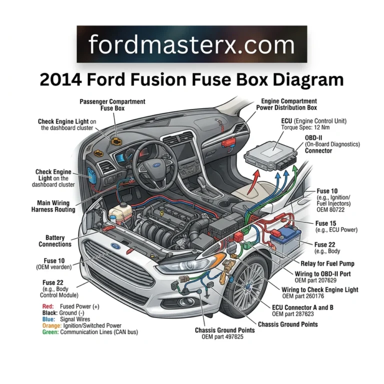
The 2011 Ford Escape features two primary fuse panels: the Battery Junction Box (BJB) located in the engine bay near the driver-side fender, and the Smart Junction Box (SJB) in the passenger footwell. Refer to the interior cover map for specific fuse amperage ratings and relay assignments controlling the ECU and OBD-II port.
📌 Key Takeaways
- The BJB houses high-amperage fuses ranging from 20A to 60A for main power distribution.
- Verify all fuses using a multimeter set to continuity mode; do not rely solely on visual inspection.
- Always disconnect the negative battery terminal before replacing high-current relays to avoid short circuits.
- Corrosion at the fuse terminal contact points is the most common cause of intermittent electrical failures.
- If a fuse blows repeatedly, seek professional diagnostic help to trace short circuits in the wiring harness.
The 2011 Ford Escape relies on a complex electrical architecture managed through two primary power distribution hubs. Understanding the 2011 Ford Escape fuse box diagram is essential for technicians and advanced DIYers tasked with maintaining the vehicle’s integrated systems, ranging from the ECU to the climate control modules. Electrical faults in these models often stem from oxidized terminals, high-resistance connections, or thermal fatigue in blade-style fuses. Whether you are addressing an intermittent check engine light or diagnosing a loss of power to the OBD-II diagnostic port, accurate identification of fuse locations and relay switching functions is the first step in successful troubleshooting. This guide provides the technical specifications required to navigate the vehicle’s electrical centers safely and efficiently.

Prime for Young Adults — 6 Months Free
Students and 18–24s get six months of Prime free, then half price.
Start 6 Months Free As an Amazon Associate I earn from qualifying purchases.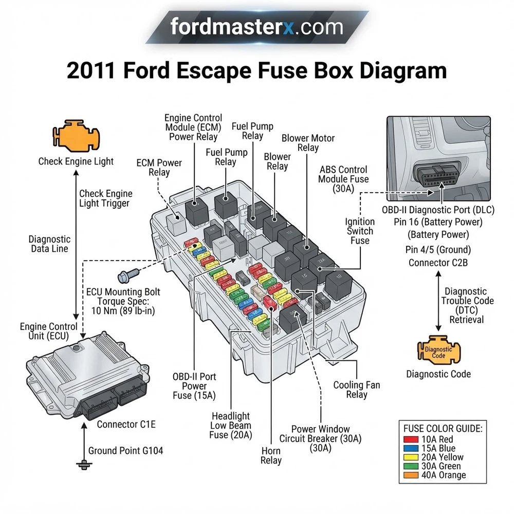
Component Identification for 2011 Ford Escape Fuse Box Diagram
Recommended Best Deal Products


To effectively service the electrical system, you must first isolate the two distinct locations where power distribution is concentrated: the Passenger Compartment Fuse Panel and the Battery Junction Box (BJB). The 2011 Ford Escape fuse box diagram layout differs slightly between the 2.5L I4 and the 3.0L V6 variants, particularly regarding cooling fan relays and ECU power supply configurations.
The Passenger Compartment Fuse Panel is located under the instrument panel on the passenger side, typically behind a removable trim cover. This panel houses fuses responsible for interior accessories, the ignition switch, and communication modules. You will find standard blade-style fuses (mini, low-profile mini, and maxi) categorized by amperage. It is imperative to check for the correct color-coded fuse corresponding to the specific circuit amperage to prevent wiring harness damage. When reviewing the diagram, pay close attention to the mini-fuses that protect the OBD-II port; a failure here often prevents scanners from establishing a link, which mimics a dead ECU.
The Battery Junction Box (BJB), positioned in the engine compartment near the air cleaner assembly, handles high-current circuits. This box contains both high-amperage cartridge fuses and standard relays. The BJB is exposed to higher thermal variations and engine vibration, making it a common site for terminal corrosion. When inspecting this box, check the relay pins for signs of arcing or carbon buildup. Relays here control heavy-load components like the fuel pump, AC compressor, and the electronic cooling fan assembly.
Always verify the physical orientation of the BJB using the embossed label on the underside of the plastic cover. Ford’s documentation can occasionally overlap between model years, but the 2011 layout is specific to the mid-cycle refresh hardware.
If you are dealing with a recurring engine performance issue, cross-reference the ECU power feed fuse in the BJB. A loose terminal here can cause transient voltage drops, leading to an erratic diagnostic code that clears itself during ignition cycles. Never substitute a fuse with one of a higher amperage rating, as the thin gauge wiring used in the cabin could melt before the fuse blows, leading to a potential electrical fire. Ensure that any replacement component matches the OEM specification found in the vehicle owner’s manual or the factory service manual.
Common 2011 Ford Escape Fuse Box Diagram Issues and Symptoms

Electrical diagnostics on this platform require a systematic approach to link symptoms to specific circuit failures. The table below outlines common failure points identified in the 2011 Ford Escape fuse box diagram.
| Circuit/System | Common Symptom | Root Cause Analysis |
|---|---|---|
| OBD-II Data Link | Scanner Link Error | Blown mini-fuse; inspect pin 16 voltage. |
| Fuel Pump Relay | Engine cranks/no start | Relay contact fatigue or open circuit. |
| Cooling Fan | Overheating at idle | Maxi-fuse failure or corroded BJB link. |
| ECU Feed | Check engine light (P0606) | High resistance in fuse block terminal. |
When dealing with a short circuit, never simply replace the fuse. A short circuit typically indicates a frayed wire insulation rubbing against the chassis or a component internally shorting to ground. Use the 2011 Ford Escape fuse box diagram to identify the branches of the circuit. For instance, if the fuel pump fuse repeatedly blows, the issue likely resides in the harness routing under the vehicle near the fuel tank. Similarly, issues with oil pressure monitoring or timing chain sensor circuits often trace back to shared ground paths located near the BJB.
Diagnostic codes involving the ECU are frequently caused by voltage fluctuations. If you observe a “U” series diagnostic code, it usually points to a CAN-bus communication failure, which is often rectified by checking the communication module fuses in the interior panel. Always use a digital multimeter to measure voltage drop across the fuse terminal before assuming the fuse itself is the culprit. A fuse with 12.6V on one side but 11V on the output side suggests significant corrosion inside the fuse block, necessitating a repair of the terminal block or a full module replacement.
Diagnosis Steps for 2011 Ford Escape Fuse Box Diagram Circuits
Recommended Best Deal Products


Troubleshooting an electrical fault requires precision. Follow these steps to verify circuit integrity using professional diagnostic tools.

Audible — Listen Free for 30 Days
One free credit a month and thousands of titles included.
Listen Free for 30 Days As an Amazon Associate I earn from qualifying purchases.1. Isolation and Visual Inspection: Begin by locating the suspected circuit via the 2011 Ford Escape fuse box diagram. Remove the fuse and inspect for signs of thermal damage, such as blackened plastic or melted casing. Use a flashlight to inspect the female spade terminals inside the fuse block for debris or signs of spread terminals.
2. Voltage Drop Testing: Use a digital multimeter set to DC volts. With the key in the “Run” position, measure the voltage at the test points on the top of the blade fuse. If the vehicle is experiencing an ECU reset or check engine light, ensure the battery is providing a stable 12.6V. If the reading at the fuse is lower than the battery voltage by more than 0.5V, there is high resistance in the feed circuit.
3. Continuity Testing: If a circuit is dead, remove the fuse and set your multimeter to the continuity or ohms setting. Check the resistance of the fuse itself. A good fuse should read near zero ohms. If the resistance is infinite, the internal element is severed.
4. Load Testing: For relays found in the BJB, use an automotive test light to verify power at the coil and the switch contacts. You can jump the load side of the relay (pins 30 and 87) to force the component to operate. If the component, such as the fuel pump or AC compressor, runs while the relay is bypassed, the relay is the likely point of failure.
Do not attempt to bypass fuses with wire or metal objects. This creates an extreme fire hazard and can permanently destroy the ECU or body control modules if a short occurs.
5. Harness Integration: If all fuses and relays check out, use your multimeter to check the harness continuity from the fuse box connector back to the component. In some cases, especially with high-mileage vehicles, internal coolant flow or oil pressure sensor wires can become brittle near the engine block, resulting in a short that blows the associated ignition or PCM fuse.
6. Final Verification: After replacing a component or cleaning a terminal, clear any pending diagnostic codes using an OBD-II scanner. Perform a test drive to ensure the check engine light does not return. If the vehicle is a 3.0L V6, be mindful of the timing chain area wiring; vibration in this zone can often lead to intermittent grounding of sensor circuits.
When reassembling the Battery Junction Box, torque fasteners to approximately 5-7 Nm. Over-torquing can crack the plastic housing, allowing moisture ingress and future electrical failure.
2011 Ford Escape Fuse Box Diagram Questions Answered
Can a faulty fuse cause a P0606 diagnostic code?
Yes. The P0606 code signifies an ECU processor fault. While this can indicate an internal ECU failure, it is frequently caused by poor voltage supply to the ECU. Check the ignition and PCM power fuses in the BJB, as well as the main ground connections to the chassis.
Are the 2011 and 2012 Ford Escape fuse boxes interchangeable?
While they appear identical, internal busbar configurations can differ due to changes in optional equipment. Always consult the 2011 Ford Escape fuse box diagram specific to your VIN to ensure compatibility with your vehicle’s specific feature set, such as trailer tow packages or different engine trims.
Audible Premium Plus — Annual Membership
12 audiobook credits up front, plus the full Audible catalogue.
See Annual Plans As an Amazon Associate I earn from qualifying purchases.How do I test an automotive relay from the BJB?
To test a relay, apply 12V to the coil terminals (usually 85 and 86) and verify that the switch terminals (30 and 87) close using a multimeter set to continuity. If you hear a click but observe no continuity, the internal contact point is pitted or oxidized and the relay must be replaced.
Why does my scanner not communicate with the OBD-II port?
This is almost always due to a blown fuse in the cigarette lighter or auxiliary power point circuit. These circuits often share a common power source with the OBD-II diagnostic port. Check the interior fuse panel for a blown fuse labeled “CIG” or “AUX” and replace as necessary.
Step-by-Step Guide to Understanding the 2011 Ford Escape Fuse Box Diagram
Recommended Best Deal Products


Identify – Consult the diagram to match the failed system symptom to the specific fuse or relay location.
Locate – Open the hood for the BJB or the passenger footwell panel for the SJB to access the modules.
Reference – Use a digital multimeter to test for voltage across the test points on the top of the suspected fuse.
Connect/Route – Secure any loose wire harness connectors leading into the box, ensuring they are seated firmly to prevent high resistance.
Verify – Clear any stored diagnostic code using an OBD-II scanner and run the engine to confirm the fix.
Troubleshoot – If the check engine light returns, inspect the ECU ground connections and verify wiring integrity for potential insulation breakdown.