2011 Ford Expedition Fuse Box Diagram: 2026 Troubleshooting Guide

The 2011 Ford Expedition features two primary power distribution boxes: the Battery Junction Box under the hood and the Smart Junction Box in the passenger footwell. The BJB houses high-amperage fuses for the starter and PCM, while the SJB controls interior circuits, ECU signaling, and OBD-II port communications.
📌 Key Takeaways
- The Battery Junction Box (BJB) manages high-load circuits ranging from 20A to 60A.
- Verify all circuits are de-energized before removing fuses to prevent electrical shorts or ECU damage.
- Maintain a strict torque spec of 10 Nm for ground strap connections to ensure stable voltage.
- Corrosion on the Smart Junction Box (SJB) pins is a frequent cause of intermittent OBD-II communication errors.
- Seek professional diagnostic assistance if you encounter active U-codes after clearing diagnostic codes.
The 2011 Ford Expedition utilizes a complex electrical architecture distributed across two primary power distribution centers. For the professional technician or advanced DIYer, navigating the 2011 Ford Expedition fuse box diagram is a critical prerequisite for diagnosing parasitic draws, intermittent lighting failures, or electronic module non-communication. Understanding the interplay between the Battery Junction Box (BJB) and the Smart Junction Box (SJB) prevents erroneous diagnostic paths, such as misidentifying a blown fuse as an ECU failure. Whether you are addressing a no-start condition or investigating a persistent check engine light, mastering these circuits ensures precision in your diagnostic workflow and long-term electrical system integrity.

Prime for Young Adults — 6 Months Free
Students and 18–24s get six months of Prime free, then half price.
Start 6 Months Free As an Amazon Associate I earn from qualifying purchases.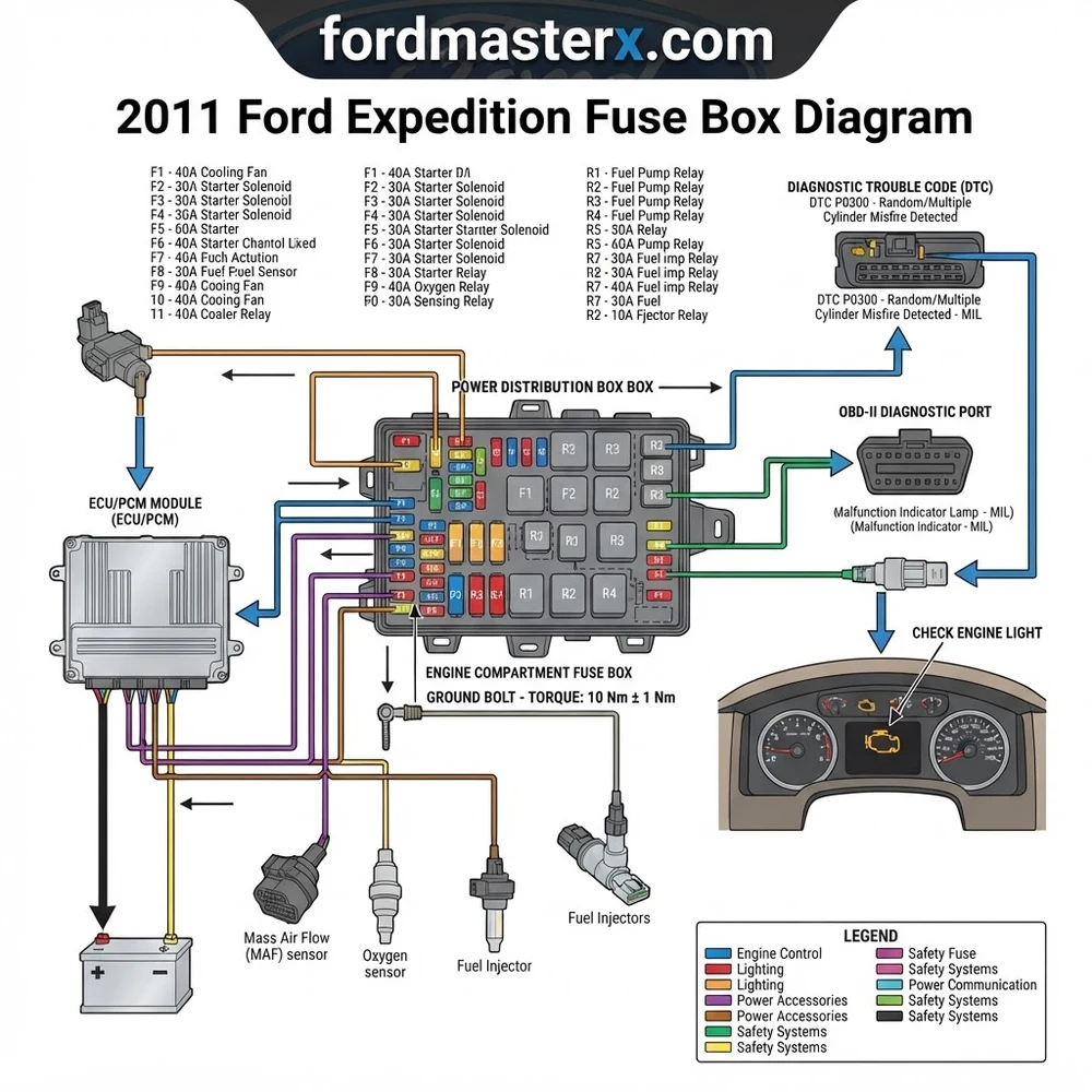
2011 Ford Expedition Fuse Box Diagram: Component Identification
Recommended Best Deal Products


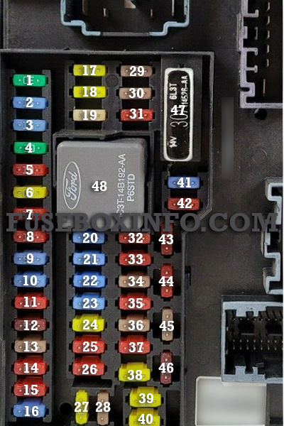
The electrical distribution system in the 2011 Ford Expedition is segmented into two high-traffic locations. The Battery Junction Box (BJB) is located in the engine compartment, typically on the passenger side near the firewall, housing high-amperage fuses and relays for major systems like the fuel pump, cooling fan, and primary power distribution. The Smart Junction Box (SJB), or Passenger Compartment Fuse Panel, is situated in the passenger side footwell, concealed behind the kick panel. This module manages logic-based circuits, interior lighting, and data bus communications.
Accurate identification requires referring to the specific owner’s manual or OEM service documentation, as variations exist based on trim levels and towing package configurations. Using the wrong fuse amperage for a circuit can lead to thermal damage in the wiring harness or permanent damage to the ECU.
| Fuse Type | Typical Location | Primary Functionality |
|---|---|---|
| Maxi Fuses | BJB (Engine) | Main power feeds, Starter, Alternator |
| Mini Fuses | SJB (Cabin) | Interior modules, Sensors, Lighting |
| Micro Relays | Both | Switching high current loads |
Battery Junction Box and Smart Junction Box Configuration
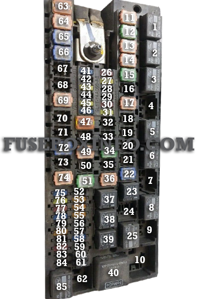
The BJB acts as the primary gateway for battery voltage. It contains the large fuse links that protect against dead shorts directly at the battery source. If your vehicle experiences a total power loss, verify the integrity of the BJB terminal connections and the primary fusible links before proceeding to the SJB. The SJB, by contrast, acts as the central hub for the CAN-bus communication system. If you identify a failure here, you may notice interior components acting erratically, such as door locks cycling or windows failing to respond to operator input. Always cross-reference the circuit numbers provided on the internal cover of the junction boxes with the official 2011 Ford Expedition fuse box diagram.
When testing the SJB, keep in mind that the unit performs localized logic control. A faulty fuse may not just cut power; it may trigger a “module offline” diagnostic code in the scan tool.
2011 Ford Expedition Fuse Box Diagram: Common Issues & Symptoms
Electrical faults in this model year often manifest as intermittent component failure or parasitic drain. Before replacing any module, use the diagram to isolate the branch circuit. If a fuse blows immediately upon replacement, you are likely dealing with a “dead short” to ground, often caused by chafed wiring in the driver’s door boot or behind the dashboard.
Analyzing Blown Fuses and Failed Relays
A blown fuse is a symptom, not the root cause. If a 15A fuse for the fuel pump keeps failing, investigate the fuel pump driver module (FPDM) for signs of oxidation or internal shorts. For lighting circuits, moisture intrusion into the rear lamp assemblies is a common culprit for shorting out the SJB-controlled lighting relays. When inspecting relays, listen for the audible “click” during activation; if no sound is present, use a jumper wire to bypass the relay load pins (30 and 87). If the component activates, you have confirmed the relay itself is faulty, rather than the control signal.
Never substitute a fuse with a higher amperage rating to bypass a recurring blown fuse. This can lead to wiring harness fires, as the wire gauge is not designed for the increased load.
Diagnosing Circuit Integrity on a 2011 Ford Expedition
Recommended Best Deal Products



Systematic diagnosis requires a digital multimeter and a firm understanding of voltage drop testing. Relying solely on a test light can lead to false positives in modern CAN-bus enabled vehicles, as the residual current may not be sufficient to light a bulb but can interfere with logic signals.
Systematic Troubleshooting Procedure
1. Perform a visual inspection of the fuse box terminals for signs of corrosion or arcing, particularly in the BJB.
2. Utilize a fuse puller tool to avoid damaging the delicate plastic tabs on the fuse blocks.
3. Set your multimeter to DC Voltage mode. Measure the voltage drop across the fuse pins while the circuit is under load; a healthy circuit should show near-zero millivolts.
4. If a circuit is dead, trace the harness back from the fuse box to the component. Look for signs of “green crust” or insulation abrasion.
5. Verify ground integrity. Many electrical gremlins on the 2011 Expedition are caused by loose ground straps near the engine block or chassis mounting points, rather than a fuse failure.

Audible — Listen Free for 30 Days
One free credit a month and thousands of titles included.
Listen Free for 30 Days As an Amazon Associate I earn from qualifying purchases.Typical chassis ground resistance should be less than 0.5 ohms. Use a high-quality multimeter to verify connections if electronic modules exhibit communication errors.
Advanced Electrical Diagnostics: ECU and OBD-II Connections
The ECU relies on constant voltage supplied through specific fuse-protected circuits. When the ECU loses communication with the OBD-II port, the first step is often to check the BJB for the Powertrain Control Module (PCM) relay and associated power fuses. A check engine light accompanied by a P0606 or U-series communication code often points toward power supply instability.
Linking Fuse Box Health to Engine Performance
Fluctuations in voltage can confuse the ECU, leading to inaccurate sensor readings. For example, unstable voltage supply to the oil pressure sensor or coolant flow sensors can lead to false dashboard warnings. Before tearing down an engine to address timing chain rattle or oil pressure concerns, ensure that the electrical sensors are receiving a steady 5V reference signal from the ECU. If your scan tool reports multiple unrelated codes, focus on the grounding cables and the BJB power distribution relays before assuming a major mechanical failure. Keeping the battery in peak condition is vital for this platform, as low voltage directly correlates to the failure of various electronic modules.
2011 Ford Expedition Fuse Box Diagram Questions Answered
Recommended Best Deal Products


Why does my fuel pump relay click but the engine fails to start?
This usually indicates a failure downstream from the fuse/relay. Verify that the Fuel Pump Driver Module (FPDM) is receiving voltage. Check your diagnostic code; if it is a communication error, check the SJB for loose harness connections.
Where is the primary OBD-II power fuse located?
The power for the OBD-II data port is generally managed within the Smart Junction Box (SJB). Consult your 2011 Ford Expedition fuse box diagram for the “Cigarette Lighter” or “Data Link Connector” labeled circuit, as these often share power with the OBD-II port.
Can a bad fuse cause an oil pressure light?
Yes. If the fuse supplying the instrument cluster or the ECU is compromised, the cluster may fail to receive correct signals from the oil pressure sensor, resulting in a false “Check Gauges” or “Low Oil Pressure” warning. Verify sensor voltage before replacing hardware.
How do I know if the BJB is faulty?
Look for evidence of melted plastic or discoloration on the underside of the BJB where the main battery cables enter. If a specific fuse consistently shows signs of melting without blowing, the socket pins within the BJB have likely lost their clamping force, creating high resistance and heat. Replacement of the entire junction box is the only OEM-approved repair for this condition.
Does the timing chain require specific fuse box configurations?
While the timing chain is mechanical, modern Expedition V8 engines use Variable Camshaft Timing (VCT) solenoids. These are electronically controlled and protected by circuits in the BJB. If a fuse associated with the VCT solenoids blows, the ECU may trigger a check engine light for timing deviation or poor engine performance. Always verify electrical supply to the VCT solenoids before assuming the timing chain or phasers are failing.
Step-by-Step Guide to Understanding the 2011 Ford Expedition Fuse Box Diagram
Identify – Locate the specific fuse box cover using the owner’s manual or diagram map.
Locate – Gain access to the Smart Junction Box in the passenger-side kick panel by removing the retention clips.
Audible Premium Plus — Annual Membership
12 audiobook credits up front, plus the full Audible catalogue.
See Annual Plans As an Amazon Associate I earn from qualifying purchases.Reference – Cross-reference your symptoms with the diagram to pinpoint the suspected relay or fuse.
Connect/Route – Connect an OBD-II scanner to verify if the electrical fault matches the stored diagnostic code.
Verify – Use a multimeter to check for 12V supply at the fuse terminal with the ignition in the ‘On’ position.
Troubleshoot – Replace blown fuses with identical amperage ratings and perform a final scan to clear the check engine light.