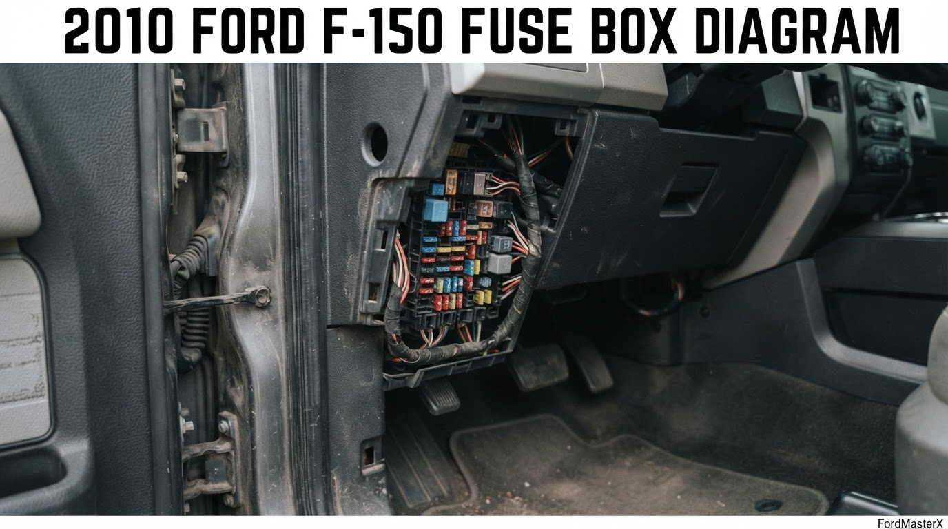
2010 Ford F-150 Fuse Box Diagram: Both Boxes, Every Fuse

Your 2010 F-150 has two fuse boxes. The Smart Junction Box sits behind the passenger side kick panel, right of the steering wheel. The power distribution box is in the engine compartment, center, above the radiator. The cigar lighter is fuse 22, rated 20A, in the engine bay box, not the cab panel.
Where are the fuse boxes on a 2010 F-150?
Recommended Best Deal Products


Both boxes carry real fuses on this truck, not just relays.

Prime for Young Adults — 6 Months Free
Students and 18–24s get six months of Prime free, then half price.
Start 6 Months Free As an Amazon Associate I earn from qualifying purchases.Smart Junction Box (passenger compartment panel). Behind the passenger side kick panel, right of the steering wheel, behind a removable cover. Pull the panel toward you, then swing it out and away from the side to remove it. This holds 47 fuse positions plus one relay.
Power distribution box. Engine compartment, center, above the radiator, also called the Battery Junction Box. It carries 85 numbered positions split between mini fuses, cartridge (FMX/JCase) fuses, and dedicated relays, plus an auxiliary relay box on SVT Raptor trucks near the windshield.
If your truck is a 2011 or newer model instead, do not use this chart. Ford renumbered the entire Smart Junction Box for the 2011 model year, inside the same 12th generation body. Fuse 22 in this 2010 truck is park and side marker lamps at 15A. In a 2011 truck fuse 22 is the horn at 20A. See the full comparison below.
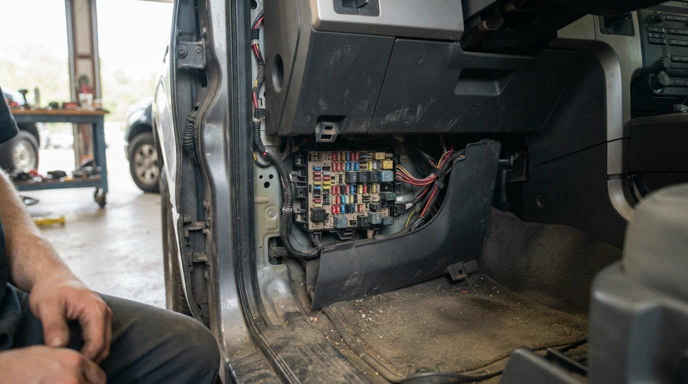
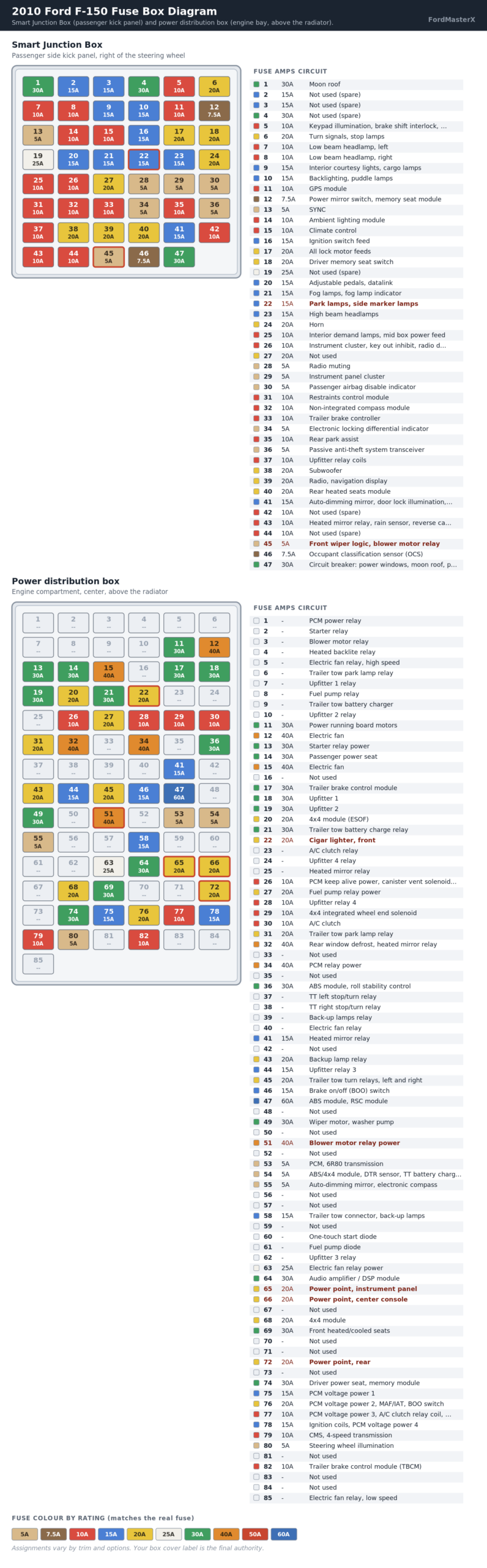
2010 F-150 Smart Junction Box fuse chart
Passenger side kick panel. All mini fuses.
| Fuse | Amps | Circuit protected |
|---|---|---|
| 1 | 30A | Moon roof |
| 2 | 15A | Not used (spare) |
| 3 | 15A | Not used (spare) |
| 4 | 30A | Not used (spare) |
| 5 | 10A | Keypad illumination, brake shift interlock, SJB power |
| 6 | 20A | Turn signals, stop lamps |
| 7 | 10A | Low beam headlamp, left |
| 8 | 10A | Low beam headlamp, right |
| 9 | 15A | Interior courtesy lights, cargo lamps |
| 10 | 15A | Backlighting, puddle lamps |
| 11 | 10A | GPS module |
| 12 | 7.5A | Power mirror switch, memory seat module |
| 13 | 5A | SYNC |
| 14 | 10A | Ambient lighting module |
| 15 | 10A | Climate control |
| 16 | 15A | Ignition switch feed |
| 17 | 20A | All lock motor feeds |
| 18 | 20A | Driver memory seat switch |
| 19 | 25A | Not used (spare) |
| 20 | 15A | Adjustable pedals, datalink |
| 21 | 15A | Fog lamps, fog lamp indicator |
| 22 | 15A | Park lamps, side marker lamps |
| 23 | 15A | High beam headlamps |
| 24 | 20A | Horn |
| 25 | 10A | Interior demand lamps, mid box power feed |
| 26 | 10A | Instrument cluster, key out inhibit, radio display, key-in chime |
| 27 | 20A | Not used |
| 28 | 5A | Radio muting |
| 29 | 5A | Instrument panel cluster |
| 30 | 5A | Passenger airbag disable indicator |
| 31 | 10A | Restraints control module |
| 32 | 10A | Non-integrated compass module |
| 33 | 10A | Trailer brake controller |
| 34 | 5A | Electronic locking differential indicator |
| 35 | 10A | Rear park assist |
| 36 | 5A | Passive anti-theft system transceiver |
| 37 | 10A | Upfitter relay coils |
| 38 | 20A | Subwoofer |
| 39 | 20A | Radio, navigation display |
| 40 | 20A | Rear heated seats module |
| 41 | 15A | Auto-dimming mirror, door lock illumination, radio accessory delay |
| 42 | 10A | Not used (spare) |
| 43 | 10A | Heated mirror relay, rain sensor, reverse camera |
| 44 | 10A | Not used (spare) |
| 45 | 5A | Front wiper logic, blower motor relay |
| 46 | 7.5A | Occupant classification sensor (OCS) |
| 47 | 30A | Circuit breaker: power windows, moon roof, power sliding backlight |
Relay in this panel: delayed accessory relay, rated 15A, feeds fuse 41 and circuit breaker 47.
Assignments vary with trim and options. Your truck may not use every position listed.
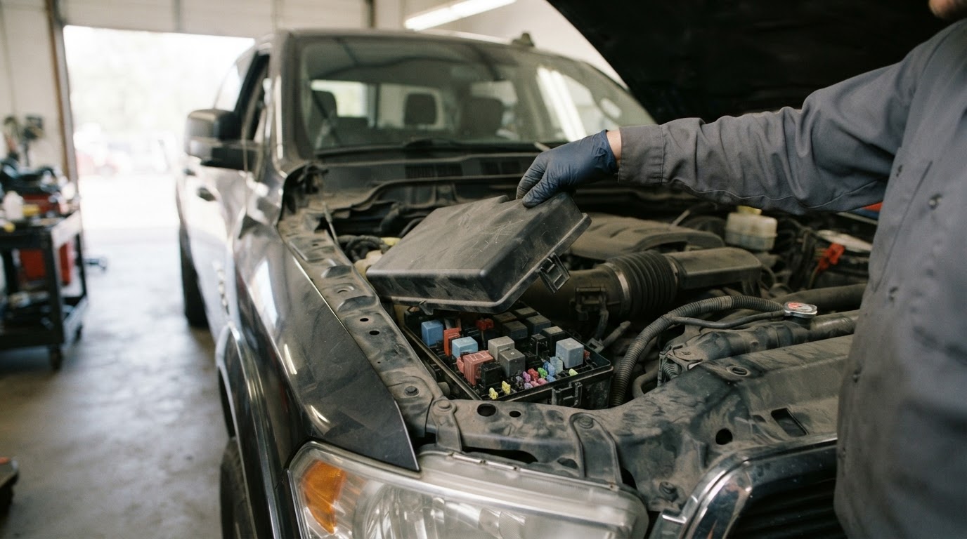
2010 F-150 power distribution box chart
Recommended Best Deal Products


Engine compartment, center, above the radiator. Full fuse and relay assignment.
| Position | Amps | Circuit protected |
|---|---|---|
| 1 | – | PCM power relay |
| 2 | – | Starter relay |
| 3 | – | Blower motor relay |
| 4 | – | Heated backlite relay |
| 5 | – | Electric fan relay, high speed |
| 6 | – | Trailer tow park lamp relay |
| 7 | – | Upfitter 1 relay |
| 8 | – | Fuel pump relay |
| 9 | – | Trailer tow battery charger |
| 10 | – | Upfitter 2 relay |
| 11 | 30A | Power running board motors |
| 12 | 40A | Electric fan |
| 13 | 30A | Starter relay power |
| 14 | 30A | Passenger power seat |
| 15 | 40A | Electric fan |
| 16 | – | Not used |
| 17 | 30A | Trailer brake control module |
| 18 | 30A | Upfitter 1 |
| 19 | 30A | Upfitter 2 |
| 20 | 20A | 4×4 module (ESOF) |
| 21 | 30A | Trailer tow battery charge relay |
| 22 | 20A | Cigar lighter, front |
| 23 | – | A/C clutch relay |
| 24 | – | Upfitter 4 relay |
| 25 | – | Heated mirror relay |
| 26 | 10A | PCM keep alive power, canister vent solenoid, 6R80 trans. |
| 27 | 20A | Fuel pump relay power |
| 28 | 10A | Upfitter relay 4 |
| 29 | 10A | 4×4 integrated wheel end solenoid |
| 30 | 10A | A/C clutch |
| 31 | 20A | Trailer tow park lamp relay |
| 32 | 40A | Rear window defrost, heated mirror relay |
| 33 | – | Not used |
| 34 | 40A | PCM relay power |
| 35 | – | Not used |
| 36 | 30A | ABS module, roll stability control |
| 37 | – | TT left stop/turn relay |
| 38 | – | TT right stop/turn relay |
| 39 | – | Back-up lamps relay |
| 40 | – | Electric fan relay |
| 41 | 15A | Heated mirror relay |
| 42 | – | Not used |
| 43 | 20A | Backup lamp relay |
| 44 | 15A | Upfitter relay 3 |
| 45 | 20A | Trailer tow turn relays, left and right |
| 46 | 15A | Brake on/off (BOO) switch |
| 47 | 60A | ABS module, RSC module |
| 48 | – | Not used |
| 49 | 30A | Wiper motor, washer pump |
| 50 | – | Not used |
| 51 | 40A | Blower motor relay power |
| 52 | – | Not used |
| 53 | 5A | PCM, 6R80 transmission |
| 54 | 5A | ABS/4×4 module, DTR sensor, TT battery charge relay |
| 55 | 5A | Auto-dimming mirror, electronic compass |
| 56 | – | Not used |
| 57 | – | Not used |
| 58 | 15A | Trailer tow connector, back-up lamps |
| 59 | – | Not used |
| 60 | – | One-touch start diode |
| 61 | – | Fuel pump diode |
| 62 | – | Upfitter 3 relay |
| 63 | 25A | Electric fan relay power |
| 64 | 30A | Audio amplifier / DSP module |
| 65 | 20A | Power point, instrument panel |
| 66 | 20A | Power point, center console |
| 67 | – | Not used |
| 68 | 20A | 4×4 module |
| 69 | 30A | Front heated/cooled seats |
| 70 | – | Not used |
| 71 | – | Not used |
| 72 | 20A | Power point, rear |
| 73 | – | Not used |
| 74 | 30A | Driver power seat, memory module |
| 75 | 15A | PCM voltage power 1 |
| 76 | 20A | PCM voltage power 2, MAF/IAT, BOO switch |
| 77 | 10A | PCM voltage power 3, A/C clutch relay coil, floor shifter |
| 78 | 15A | Ignition coils, PCM voltage power 4 |
| 79 | 10A | CMS, 4-speed transmission |
| 80 | 5A | Steering wheel illumination |
| 81 | – | Not used |
| 82 | 10A | Trailer brake control module (TBCM) |
| 83 | – | Not used |
| 84 | – | Not used |
| 85 | – | Electric fan relay, low speed |
Auxiliary relay box, SVT Raptor only, left rear corner of the engine compartment: position 1 upfitter switch 1, position 2 upfitter switch 2, position 3 upfitter switch 3, position 4 upfitter switch 4, position 5 not used, position 6 not used.
What changes between a 2010 and 2011 F-150 (most sites miss this)
The 2009 to 2014 F-150 is one truck generation, so most fuse sites publish a single combined chart for all six model years. That merge hides a full renumbering that lands right after this truck.
Ford kept the 2009 and 2010 Smart Junction Box layout close to identical, then rebuilt it for 2011 and carried that new layout through 2014 unchanged. Position numbers, fuse counts and even the circuit groupings moved. Here is what fuse 22 alone does across the range:

Audible — Listen Free for 30 Days
One free credit a month and thousands of titles included.
Listen Free for 30 Days As an Amazon Associate I earn from qualifying purchases.| Model years | Fuse 22 location | Fuse 22 circuit | Amps |
|---|---|---|---|
| 2009 to 2010 | Smart Junction Box (cab) | Park lamps, side marker lamps | 15A |
| 2011 to 2014 | Smart Junction Box (cab) | Horn | 20A |
| 2009 to 2014 | Power distribution box (engine bay) | Cigar lighter | 20A |
Fuse 22 exists in both boxes on every model year in this generation, doing two unrelated jobs at once. Search “fuse 22” and you could be looking for either one. This is why the box matters as much as the number: always say cab panel or engine bay, never just the position.
The power distribution box itself did not get renumbered the same way, but two of its positions do change later in the generation. Fuses 16 and 35 are not used on this 2010 truck, on every 2009 through 2012 model, then become active 20A HID headlamp fuses starting with the 2013 model year. Our own 2013 Ford F-150 fuse box diagram covers that later change. A single merged 2009-2014 chart, or one that pulls its power distribution box table from a 2013 or 2014 source, would print two fuses this truck does not use.
I cross-checked this against StartMyCar’s 2010-specific page, sourced from the Ford Owner’s Manual, Ricks Free Auto Repair Advice’s 2010-specific fuse index, and fuse-box.info’s year-split tables, which show 2009 and 2010 under the same diagram image and switch to a different one starting at 2011. All three agree on the split point and on nearly every value in this article.
Two positions are open disagreements, resolved here by majority rather than silently picked. FuseAndRelay’s combined 2009-2014 table lists power distribution box fuse 22 as “30A, auxiliary power point,” which conflicts with its own summary sentence naming that same fuse the cigar lighter, and with all three other sources at 20A. Ricks Free Auto Repair Advice lists Smart Junction Box fuse 45 (front wiper logic, blower motor relay) at 10A, where StartMyCar, FuseAndRelay’s 2009-2010 table and fuse-box.info all agree on 5A. This article uses the three-source majority in both cases. Your box cover label is the final authority if your truck disagrees.
Which fuse is the cigar lighter and 12V power point?
Recommended Best Deal Products


On this 2010 F-150 the cigar lighter is fuse 22, rated 20A, in the power distribution box under the hood. It is not in the cab panel, where fuse 22 is a different circuit entirely.
The other power points live in the same engine bay box: fuse 65, 20A for the instrument panel point, and fuse 66, 20A for the center console point, and fuse 72, 20A for the rear point.
Ford does not publish a single combined “power point” fuse for this truck. Each socket location has its own dedicated position, so a dead rear outlet does not mean the front cigar lighter is affected, and the reverse is also true.
Which fuse controls the radio?
Two fuses cover the audio system on this truck, both in the Smart Junction Box.
- Fuse 39, 20A: radio, navigation display. Main feed. Blow this and the head unit goes dark.
- Fuse 26, 10A: instrument cluster, radio info display, radio buttons, key-in chime. Screen and chime specific. A dead radio display with the unit otherwise powering on points here first.
Fuse 38, 20A, feeds the subwoofer separately, and the amplifier draws from fuse 64, 30A, in the power distribution box. Main speakers working while the subwoofer stays silent points at fuse 38, not 39.
Which fuse controls the A/C, blower and heated seats?
Comfort circuits split across both boxes, so the symptom tells you which box to open.
Audible Premium Plus — Annual Membership
12 audiobook credits up front, plus the full Audible catalogue.
See Annual Plans As an Amazon Associate I earn from qualifying purchases.| Symptom | Check this | Box |
|---|---|---|
| Fan blows but never gets cold | Fuse 30, 10A, A/C clutch, plus relay 23 | Engine bay |
| No air at any speed | Fuse 51, 40A, blower motor relay power, plus relay 3 | Engine bay |
| Climate controls dead | Fuse 15, 10A, climate control | Cab panel |
| Front wiper and blower logic both act up together | Fuse 45, 5A, front wiper logic and blower motor relay | Cab panel |
| Rear heated seats not working | Fuse 40, 20A | Cab panel |
| Front heated or cooled seats not working | Fuse 69, 30A | Engine bay |
The blower is the one people get wrong most. It is a 40A cartridge fuse in the engine bay, not a mini fuse in the cab. If the fan works on high but nothing else, the fuse is fine and the blower motor resistor is the more likely part.
Fuse 45 is worth a second look. It shares front wiper logic and the blower motor relay signal on the same 5A mini fuse, so a wiper that stopped parking correctly alongside a blower acting strangely both trace back here before you replace either part.
Which fuse stops the truck from starting?
Several positions can leave you turning the key with nothing happening.
- Relay 2, engine bay. Starter relay. No click at all points here first.
- Fuse 13, 30A, engine bay. Starter relay power.
- Relay 8 and fuse 27, 20A, engine bay. Fuel pump relay and its power feed. Engine cranks but will not fire.
- Fuse 34, 40A, engine bay. PCM relay power. No crank and no dash lights together points here before the starter itself.
- Fuse 5, 10A, cab panel. Keypad illumination, brake shift interlock, SJB microprocessor power. If the shifter will not release from park alongside a no-start, check this circuit before assuming a shifter or module fault.
No crank at all points at the starter relay chain (2, 13). Cranks but will not fire points at fuel delivery (8, 27) or ignition coil power (fuse 78).
How do you tell if a fuse is actually blown?
Pull it and look through the plastic window at the metal strip. An intact fuse has an unbroken element. A blown one shows a visible gap, or the window is smoked brown or black.
Three things catch people out on this truck:
- A hairline break looks intact. Hold the fuse to a light. If you are not certain, test continuity with a multimeter set to ohms. Near zero means good.
- Never guess the replacement rating. Match the number printed on the fuse and cross-check the box cover label. Fitting a 40A fuse where a 20A belongs lets the wiring become the fuse.
- The engine bay box mixes fuse types. Positions in the 11 to 22 range and several others are FMX/JCase cartridge fuses that need a puller, while most of the rest are mini fuses. Pliers crack the cartridge housing. A mixed ATO/ATC fuse assortment kit costs less than one dealer fuse and usually includes the puller.
Why does the same fuse keep blowing?
A fuse that blows once is usually a surge. One that blows again within days means the fault is upstream, and replacing it repeatedly treats the alarm instead of the fire.
Work through it in this order:
- Unplug whatever you added most recently. Trailer wiring, a dash cam, an aftermarket stereo, a charger left in a power point. Aftermarket accessories cause most repeat blows on these trucks.
- Check where the harness moves. Door jambs, the tailgate run, and anything near the steering column flex thousands of times and chafe.
- Look for water. A wet connector shorts intermittently, which is why the fuse survives a dry week and dies in the rain.
Trailer tow circuits on this truck have their own habit worth knowing. Fuses 17, 21, 31 and 45 in the power distribution box, plus fuse 33 in the cab panel, all feed trailer relays, and a corroded seven-pin connector is the usual culprit behind repeat blows there.
If a fuse blows the instant you seat it, there is a hard short. Stop replacing fuses and trace the circuit. A Ford-capable scan tool reads live data instead of guessing, and if the OBD-II port itself will not link, that datalink circuit shares fuse 20 in the cab panel with the adjustable pedal switch.
2010 F-150 fuse quick reference
The positions owners look up most, in one place. C means the Smart Junction Box (cab), E means the power distribution box (engine bay).
| What you want | Fuse | Amps | Box |
|---|---|---|---|
| Cigar lighter, front 12V outlet | 22 | 20A | E |
| Instrument panel power point | 65 | 20A | E |
| Center console power point | 66 | 20A | E |
| Rear power point | 72 | 20A | E |
| Radio, navigation display | 39 | 20A | C |
| Park and side marker lamps | 22 | 15A | C |
| Horn | 24 | 20A | C |
| Fuel pump relay power | 27 | 20A | E |
| Starter relay power | 13 | 30A | E |
| High beam headlamps | 23 | 15A | C |
| Low beam, left | 7 | 10A | C |
| Low beam, right | 8 | 10A | C |
| Fog lamps | 21 | 15A | C |
| Wiper motor, washer pump | 49 | 30A | E |
| Blower motor | 51 | 40A | E |
| A/C clutch | 30 | 10A | E |
| Front heated or cooled seats | 69 | 30A | E |
| Rear heated seats | 40 | 20A | C |
| Power windows, moon roof, sliding backlight | 47 | Breaker, 30A | C |
| All power door lock motors | 17 | 20A | C |
| Driver power seat, memory | 74 | 30A | E |
| Trailer brake controller | 33 | 10A | C |
| Trailer brake control module | 17 | 30A | E |
| Datalink connector (OBD-II) | 20 | 15A | C |
Our 2006 Ford F-150 fuse box diagram covers the previous generation truck, where the cigar lighter fuse and box layout are both different again. Our 2011 Ford F-150 fuse box diagram and 2013 Ford F-150 fuse box diagram cover the renumbered cab panel that starts the model year after this one. If your truck is a 2011 model or newer, use those instead, since the Smart Junction Box numbering does not match this chart.