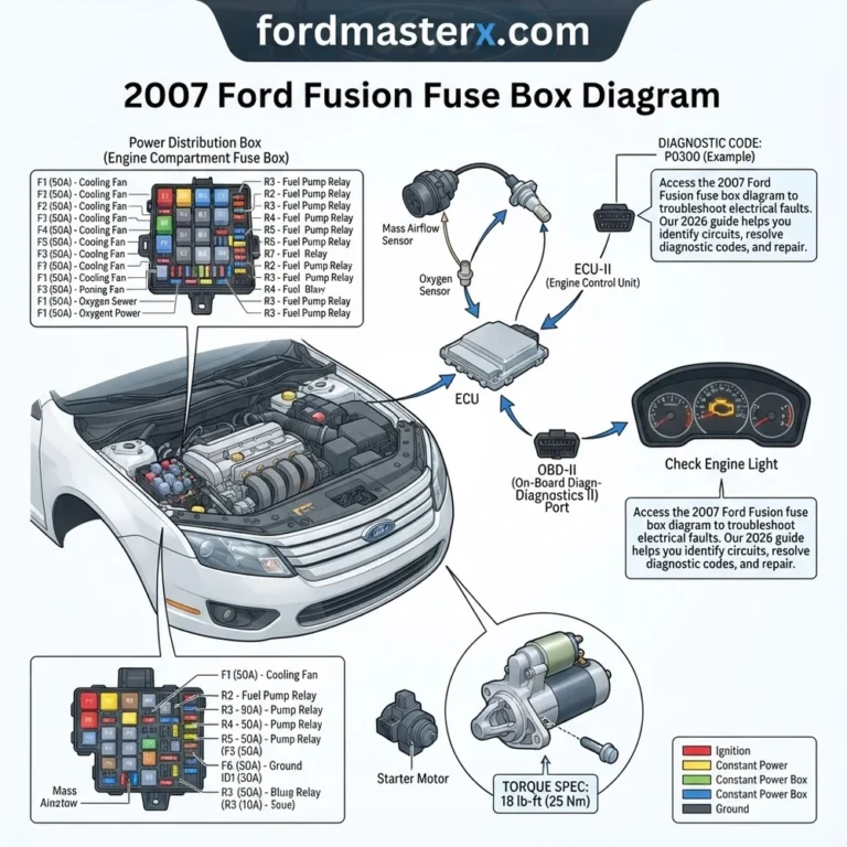
2002 Ford Taurus Fuse Box Diagram: Component Identification 2026

The 2002 Ford Taurus features two primary fuse panels: the interior passenger compartment fuse box located under the instrument panel, and the power distribution box in the engine bay near the driver-side fender. Always verify amperage ratings (e.g., 10A, 20A) before replacement; mismatched fuses can damage the ECU or sensor wiring.
📌 Key Takeaways
- The interior panel covers cabin accessories, while the engine bay box handles high-load relays and ECU power.
- Always use a plastic fuse puller to avoid damaging metal terminal pins within the block.
- Ensure the battery is disconnected when inspecting high-amperage Maxi-fuses to prevent arcing.
- A blown fuse is often a symptom; if a replacement blows immediately, check for a direct short in the circuit.
- Refer to the owner’s manual for specific torque specs if removing the entire power distribution module.
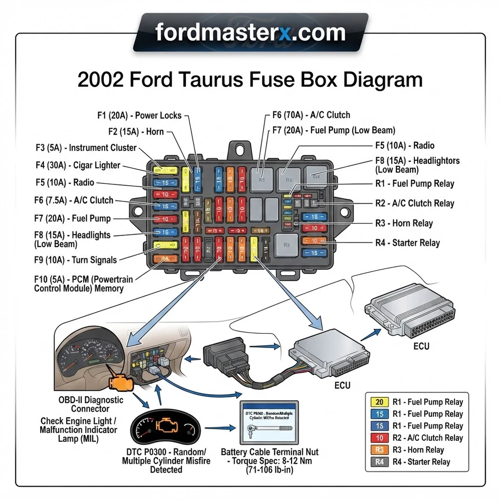
A functional 2002 Ford Taurus relies on a robust electrical system, and understanding its fuse box layout is paramount for effective maintenance and troubleshooting. This comprehensive guide delves into the intricacies of the 2002 Ford Taurus fuse box diagram, equipping automotive professionals and seasoned DIYers with the knowledge to identify components, interpret the schematic, and diagnose common electrical issues. From pinpointing the location of fuses and relays controlling vital systems like the ECU to understanding how to interpret diagnostic codes that might indicate an electrical fault, this article serves as your definitive resource for the 2002 Ford Taurus’s electrical nerve center. We will explore how a blown fuse can manifest as a check engine light or a complete system failure, and how to use this diagram to systematically address such problems, ensuring your Taurus remains in optimal working condition.

Prime for Young Adults — 6 Months Free
Students and 18–24s get six months of Prime free, then half price.
Start 6 Months Free As an Amazon Associate I earn from qualifying purchases.2002 Ford Taurus Fuse Box Diagram: Component Identification and Layout
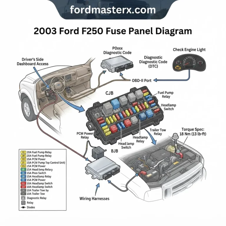
The electrical architecture of the 2002 Ford Taurus features two primary power distribution locations: the Central Junction Box (CJB) and the Battery Junction Box (BJB). Each serves distinct functions and houses a specific arrangement of fuses and relays that safeguard various vehicle circuits. Accurately identifying these components is the foundational step to any successful electrical diagnosis. The CJB, often located within the passenger compartment, typically manages interior electronics, lighting, and accessory power. The BJB, usually situated in the engine compartment, is responsible for higher-draw circuits, including those feeding the ECU, ignition system, and cooling fans. Understanding the physical layout and the corresponding labels on these boxes is crucial.
The fuses are designed to protect circuits from overcurrents. They contain a thin wire element that melts and breaks the circuit if the amperage exceeds its rated value. Relays, on the other hand, act as electrically operated switches, allowing a low-current circuit (like a switch in the dashboard) to control a high-current circuit (like the starter motor or headlights). The diagrams printed on the fuse box covers, or sometimes found on the inside of the cover or within the owner’s manual, are your primary reference for correlating fuse or relay positions with specific vehicle functions. For instance, a blown fuse labeled “Cigar Lighter” will clearly indicate that the power outlet is not functioning due to a protection device. Similarly, a malfunctioning relay for the fuel pump might prevent the engine from starting, necessitating a check of the relay’s dedicated socket.
Here’s a breakdown of common components and their significance within the 2002 Ford Taurus fuse box diagram:
| Component Type | Function | Typical Location |
|---|---|---|
| Fuses | Circuit protection; melts to break current flow. | Both CJB and BJB. Labeled with amperage (e.g., 10A, 15A, 20A) and circuit name. |
| Relays | Electrically operated switches controlling higher current circuits. | Both CJB and BJB. Labeled with function (e.g., Fuel Pump Relay, Horn Relay). |
| Central Junction Box (CJB) | Manages interior electronics, lighting, accessories, and some powertrain modules. | Typically under the dashboard, driver’s side. |
| Battery Junction Box (BJB) | Supplies power to major engine components, starting system, and high-current accessories. | Engine compartment, often near the battery. |
| ECU (Engine Control Unit) Fuse/Relay | Provides power and control signals to the vehicle’s primary computer. Critical for engine operation. | Varies; check diagram for specific location, often in BJB or dedicated module. |
When referring to the 2002 Ford Taurus fuse box diagram, always ensure you are referencing the correct box. A fuse controlling the interior dome light will be located in the CJB, while a fuse for the cooling fan system will be in the BJB. Understanding the relationship between these boxes and the vehicle’s electrical demands is key. For instance, the OBD-II port, used for accessing diagnostic codes, is powered by a circuit protected by a fuse, and knowing its location on the diagram can aid in diagnosing power issues to the diagnostic port itself.
Locating and Interpreting the 2002 Ford Taurus Fuse Box Diagrams
Accessing and correctly interpreting the 2002 Ford Taurus fuse box diagram is a critical step before any component replacement or diagnostic procedure. Ford vehicles, including the 2002 Taurus, typically provide this vital information in a clear and accessible manner. The primary source will be your vehicle’s owner’s manual. Within the manual, there will be a dedicated section detailing the fuse box locations and a graphical representation of each fuse box. These diagrams are usually printed with clear labels corresponding to fuse and relay positions, along with their amperage ratings and the circuits they protect. Pay close attention to any specific notes or symbols used in the diagram, as they can indicate special fuse types or functionalities.
The physical fuse boxes themselves are often covered. In the passenger compartment, the CJB cover might be secured with clips or small screws and is usually found by reaching under the dashboard, typically on the driver’s side. In the engine compartment, the BJB cover will likely be more robust, often secured with clips or fasteners to protect its contents from the elements. Once the covers are removed, you will see the array of fuses and relays. The numbers or symbols printed directly on the fuse box housing should correspond directly to the 2002 Ford Taurus fuse box diagram you are referencing from your owner’s manual.
A common point of confusion can arise from slightly different fuse box layouts between model years or specific trim levels. Always ensure you are referencing the diagram specifically for your 2002 Ford Taurus. The owner’s manual is the most authoritative source. If you do not have your owner’s manual, reputable automotive repair websites or specialized Ford forums can often provide PDF versions or detailed diagrams for your specific year and model.

Audible — Listen Free for 30 Days
One free credit a month and thousands of titles included.
Listen Free for 30 Days As an Amazon Associate I earn from qualifying purchases.The “terminal” refers to the connection points for fuses and relays. When a fuse blows, you are looking at the fuse itself, which sits within its designated terminal. Relays also occupy specific terminals. Understanding the layout means you can trace a circuit. For example, if you’re experiencing an issue with the cooling fan, the 2002 Ford Taurus fuse box diagram will guide you to the fuse and relay controlling the fan system. You can then physically locate these components in the BJB. The “junction block” is a more general term that can refer to a collection of terminals or a component where multiple circuits converge. In the context of fuse boxes, the fuse box itself acts as a primary junction block for power distribution.
Beyond the owner’s manual, some vehicles have a diagram printed on the inside of the fuse box cover itself. This is a convenient, at-a-glance reference, but it’s always best to cross-reference with the owner’s manual for complete accuracy. If you are investigating an intermittent electrical issue, understanding the flow of current indicated by the diagram can be invaluable. For instance, tracing the power supply to the ECU can reveal if a fuse or relay failure is the cause of a check engine light or starting problem. Similarly, when dealing with issues related to coolant flow, understanding the fuses and relays for the cooling fans is a logical first step.
INFO BOX:
For 2002 Ford Taurus models, ensure you are consulting a diagram specific to its production date and any optional equipment packages, as minor variations can occur. If you suspect an issue with the OBD-II system, verifying the power supply to the diagnostic port via its associated fuse is a foundational diagnostic step.
Common 2002 Ford Taurus Fuse Box Diagram Issues and Symptoms
Electrical gremlins can manifest in numerous ways, and a blown fuse is one of the most common culprits for a sudden failure of a vehicle system. Recognizing the symptoms associated with faulty fuses and relays is crucial for efficient troubleshooting using the 2002 Ford Taurus fuse box diagram. Often, a dead circuit is the most obvious sign: a component or system simply stops working. This could range from interior lights and power windows failing to more critical functions like the fuel pump or ignition system becoming inoperative.
An “open circuit” is precisely what happens when a fuse blows. The conductive element inside the fuse melts, creating a gap, thus interrupting the flow of electricity. If a particular circuit is experiencing a “short to ground,” meaning a hot wire is accidentally making contact with the vehicle’s chassis, an excessive amount of current will flow. This high current will quickly blow the fuse designed to protect that circuit. The key is to identify which circuit is affected to pinpoint the correct fuse on the diagram.
The “amperage rating” of a fuse is critical. Fuses are designed with specific ratings (e.g., 10A, 15A, 20A) to protect the wiring and components from damage due to overcurrent. Never replace a blown fuse with one of a higher amperage rating, as this can lead to melted wires, component damage, or even a fire. Always replace a blown fuse with one of the exact same amperage and type. If a fuse blows repeatedly, it indicates an underlying electrical problem that needs to be diagnosed, rather than just a simple fuse failure. This could point to a short circuit, a faulty component drawing too much current, or a wiring issue.
Relays, while not designed to “blow” like fuses, can also fail. A common relay failure is when the “relay coil” burns out or becomes stuck. This can cause the associated circuit to either remain constantly on or fail to activate altogether. For example, a faulty fuel pump relay might prevent the pump from running, leading to a no-start condition. Conversely, a stuck cooling fan relay could cause the fans to run continuously, draining the battery.
Symptoms that might point to a fuse or relay issue include:
Complete system failure: A specific electrical component or system stops working entirely (e.g., radio, headlights, power locks).
Intermittent operation: A component works sometimes but not others, often correlated with temperature changes or vibration.
Check Engine Light illumination: While often related to engine performance or emissions, a faulty fuse or relay in a critical system like the ECU or fuel injection can trigger this light.
No-start condition: Problems with the starter relay, fuel pump relay, or ECU power can prevent the engine from cranking or firing.
Overheating: A blown fuse or faulty relay for the cooling fans can lead to engine overheating, impacting coolant flow.
Strange electrical behavior: Dimming lights, flickering displays, or unexpected activation of accessories can sometimes be traced back to a shared circuit or a faulty relay.
Audible Premium Plus — Annual Membership
12 audiobook credits up front, plus the full Audible catalogue.
See Annual Plans As an Amazon Associate I earn from qualifying purchases.When faced with any of these symptoms, consulting the 2002 Ford Taurus fuse box diagram and systematically checking the relevant fuses and relays is a logical and often effective first step. Understanding the diagram will allow you to quickly identify which fuse or relay is responsible for the affected system, saving valuable diagnostic time. This is particularly important when troubleshooting issues that might be related to engine performance, such as those affecting oil pressure readings or the timing chain operation indirectly through power supply to sensors.
SPEC BOX:
Standard fuse types for the 2002 Ford Taurus include blade-type fuses (ATO/ATC), mini-blade fuses, and potentially some high-current cartridge fuses. Relay types will vary, but commonly include standard automotive relay sockets. Always use the specified amperage and type when replacing.
Diagnosis Steps for 2002 Ford Taurus Electrical Circuits
Diagnosing electrical faults in your 2002 Ford Taurus, particularly those related to the fuse box, requires a methodical approach and the right tools. The 2002 Ford Taurus fuse box diagram serves as your roadmap, but verifying the condition of fuses, relays, and the circuits they control is essential. For experienced technicians and capable DIYers, utilizing an automotive multimeter and a test light are fundamental.
Here’s a step-by-step diagnostic process:
1. Identify the Affected System and Consult the Diagram: First, determine which electrical component or system is malfunctioning. Refer to your 2002 Ford Taurus fuse box diagram (from the owner’s manual or cover) to locate the fuse and/or relay(s) responsible for that specific circuit. Note the amperage rating of the fuse and the type of relay.
2. Visual Inspection of Fuses and Relays:
Fuses: Carefully remove the suspect fuse. Hold it up to a light source. Inspect the conductive metal strip inside. If it appears broken, melted, or disconnected, the fuse is blown and needs replacement.
Relays: While visual inspection of relays is less definitive, check for any signs of physical damage, corrosion, or burnt terminals.
3. Test Fuse Continuity: Even if a fuse looks good, it might be internally open.
Use an automotive multimeter set to continuity mode (often indicated by a sound wave symbol or “Ω”).
With the fuse removed from the box, place the multimeter probes on each of the fuse’s metal prongs.
A good fuse will show continuity (a low resistance reading, often accompanied by a beep). A blown fuse will show no continuity (an open circuit or infinite resistance reading).
4. Test Relay Functionality: Relays are more complex to test directly in the vehicle without specialized equipment, but you can perform basic checks.
Swap Test: If you have a known good, identical relay from a non-critical circuit (e.g., horn relay if the horn isn’t working and it’s a different relay than the one you suspect), try swapping it into the suspected relay’s socket. If the problem resolves, the original relay was faulty. Always use a relay of the exact same part number and specifications.
Power and Ground Check: With the relay in its socket and the ignition on (if applicable), use your multimeter to check for power and ground at the relay’s socket terminals. This verifies that the relay is receiving the necessary inputs.
5. Check for Power at the Component: Once you’ve confirmed the fuse and relay are good, or have replaced a suspected faulty one, use a test light or multimeter to verify that power is reaching the affected component.
Connect the test light to ground.
With the ignition on (as required for the circuit), carefully probe the power input terminal of the component.
If the test light illuminates, power is reaching the component. If not, the fault lies further upstream in the wiring or a related fuse/relay.
6. Check for Voltage Drop: If power is present but the component still doesn’t work, check for voltage drop across fuses, connectors, and wiring. Excessive voltage drop indicates high resistance in the circuit.
Set your multimeter to DC voltage.
With the circuit under load (e.g., component powered on), measure the voltage between the positive terminal of the power source and the positive terminal of the component. A significant voltage drop (more than 0.5V) indicates a problem.
7. Inspect Wiring and Connectors: Look for any signs of damaged, frayed, corroded, or loose wiring and connectors in the vicinity of the fuse box, the affected component, and along the circuit path. Poor connections are a common cause of intermittent electrical issues.
8. Consider ECU and Sensor Interactions: For more complex issues, especially those triggering a check engine light, remember that fuses and relays provide power to the ECU and various sensors. A fault in these power circuits can directly impact engine performance, potentially leading to symptoms related to oil pressure or even affecting timing chain synchronization due to sensor input loss. Always follow the diagnostic flowcharts in a service manual for specific DTC (Diagnostic Trouble Code) related issues.
WARNING BOX:
Always disconnect the vehicle’s battery before performing any electrical repairs or replacements. Ensure you are using the correct tools and safety precautions. Never work on live electrical circuits unless the diagnostic procedure specifically requires it, and then only with extreme caution and appropriate personal protective equipment.
2002 Ford Taurus Fuse Box Diagram: Frequently Asked Questions
Where are the fuse boxes located in a 2002 Ford Taurus?

The 2002 Ford Taurus typically has two main fuse box locations. The Central Junction Box (CJB) is generally found within the passenger compartment, often under the dashboard on the driver’s side. The Battery Junction Box (BJB) is usually located in the engine compartment, frequently near the battery, and houses fuses and relays for major powertrain and high-current circuits.
How do I know which fuse to check if my headlights aren’t working?
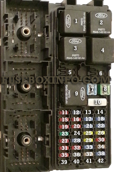
Consult the 2002 Ford Taurus fuse box diagram in your owner’s manual. It will clearly label the fuse(s) and relay(s) responsible for the headlight system. Look for designations like “Headlamps,” “Low Beams,” or “High Beams.” The diagram will specify the location in either the CJB or BJB and the amperage of the fuse. A blown fuse here is a common cause for non-functioning headlights.
What does it mean if a fuse blows repeatedly?
If a fuse blows shortly after installation, it indicates an underlying electrical fault in that circuit. This is often a “short to ground,” where a hot wire is making unintended contact with the vehicle’s chassis, or a component is drawing excessive current. Simply replacing the fuse repeatedly will not fix the problem and could lead to further damage. The circuit needs to be diagnosed to find and repair the short or fault.
Can a blown fuse cause a check engine light to appear?
Yes, a blown fuse can certainly cause a check engine light to illuminate. Many critical engine components, sensors, and modules rely on specific fuses for power. If the fuse protecting the ECU, a sensor circuit (like for engine speed or manifold pressure), or a fuel system component fails, the engine control module may detect a fault and trigger the check engine light. Checking relevant fuses is a fundamental diagnostic step when a DTC is present.
What is the difference between a fuse and a relay in the 2002 Ford Taurus fuse box diagram?
A fuse is a passive safety device designed to protect a circuit from overcurrent by melting its internal wire. A relay is an electrically operated switch. It uses a small amount of current to control a larger current, allowing a low-power signal (like from a dashboard switch) to activate a high-power device (like the starter motor or fuel pump). The 2002 Ford Taurus fuse box diagram will show distinct symbols and locations for each.
Step-by-Step Guide to Understanding the 2002 Ford Taurus Fuse Box Diagram
Recommended Best Deal Products


Identify – Locate the fuse panel covers in the cabin and engine bay.
Locate – Compare the diagram to the physical layout to find the suspected circuit.
Reference – Cross-check the blown fuse amperage with the manufacturer specifications.
Connect/Route – Secure any loose relay connections or clean corroded pins if needed.
Verify – Perform a diagnostic code sweep via the OBD-II port to ensure no ECU errors remain.
Troubleshoot – Test the circuit with a multimeter if the new fuse blows immediately.
2002 Ford Taurus Fuse Box Diagram: Frequently Asked Questions
What does the 2002 ford taurus fuse box diagram show?
The diagram displays the physical layout and amperage ratings for every fuse and relay in the vehicle. It identifies specific circuits for the fuel pump, ignition system, headlights, and ECU, allowing you to trace power distribution paths when electrical components fail or diagnostic codes appear.
How do I read the 2002 ford taurus fuse box diagram?
Match the visual layout on the diagram to the physical arrangement inside your fuse box covers. Each slot is numbered and color-coded by amperage. Compare these to the chart provided in your manual to identify the exact circuit powering your malfunctioning component or triggering a check engine light.
What are the main components in 2002 ford taurus fuse box diagram?
Main components include blade-style fuses (Mini, ATO, Maxi), standard ISO relays, and circuit breakers. These manage power flow from the battery to vital systems like the OBD-II port, ECU, lighting controls, and climate systems, ensuring protected operation of all electronic modules throughout the Taurus chassis.
What are common problems with 2002 ford taurus fuse box diagram?
Common issues involve oxidation on terminal pins, loose relay seating, or water intrusion in the engine bay box. These lead to intermittent power, blown fuses without a clear cause, or communication errors between the ECU and OBD-II port, often requiring terminal cleaning or housing replacement.
Can I use 2002 ford taurus fuse box diagram for DIY repair?
Yes, it is the primary reference for DIY troubleshooting. Use it to verify circuit continuity before replacing expensive sensors. However, if the issue involves melted wiring or significant electrical damage, consult a professional mechanic to prevent further damage to the wiring harness or electronic modules.
What tools do I need for 2002 ford taurus fuse box diagram?
You need a non-conductive plastic fuse puller, a digital multimeter to check voltage drop or continuity, and a flashlight. If checking for shorts, an OBD-II scanner is essential to read diagnostic codes that might point toward specific fused circuits related to engine performance or emissions.