Ford 7.3 Godzilla Engine Diagram: Full Component Guides 2026

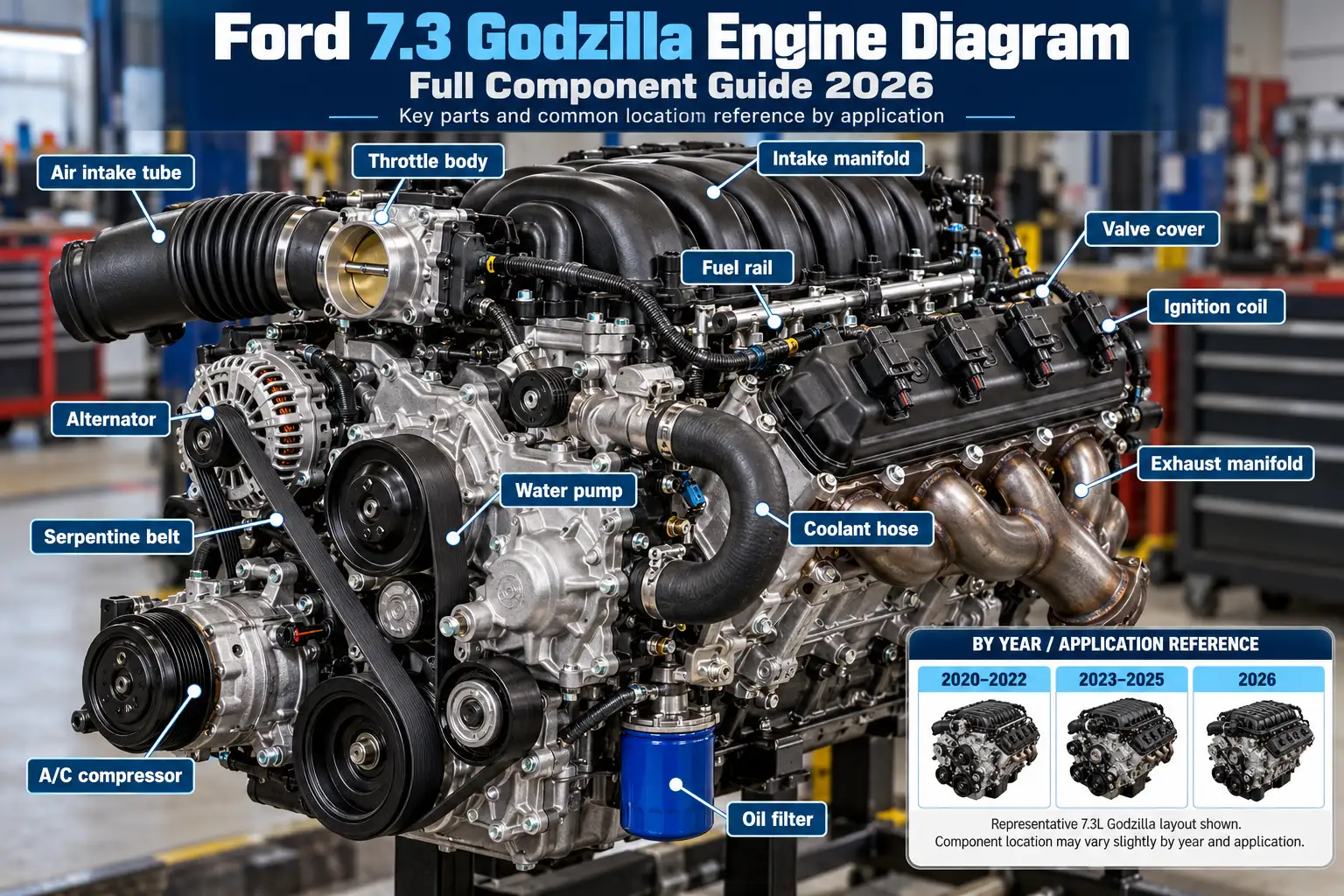
The Ford 7.3 Godzilla engine diagram helps you identify the major parts of Ford’s 7.3L gasoline V8, from the intake and cylinder heads to its camshaft, timing drive, and accessory belts. The engine is used in Super Duty trucks and other Ford commercial applications, but the under-hood arrangement changes with the vehicle and its equipment.


The reference layouts below explain the engine’s construction, the 2026 Super Duty service points, cylinder numbering, and the correct firing order. This is the gasoline Godzilla V8, not the older 7.3L Power Stroke diesel. Use your truck’s model-year-specific Ford manual before following a diagram for parts removal or belt replacement.
Find each cylinder by bank and position, then read the factory firing sequence. Original reference graphic based on Ford’s published 7.3L information.
Top-down reference. The front of the vehicle is at the bottom. Numbers are physical cylinder positions, not the firing sequence.
MANIFOLD V-engine valley
The eight digits show the order cylinders fire; they do not show their left-to-right or front-to-rear positions.
Technical references: Ford Performance 7.3L Engine Control Pack instructions (M-6017-73A) and Ford 7.3L engine specifications. Original illustration; not a Ford factory reproduction.
What Does the Ford 7.3 Godzilla Diagram Show
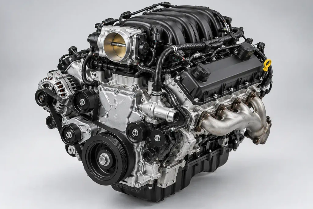
The Godzilla is a longitudinal, naturally aspirated V8. Its composite intake manifold sits above the two cylinder banks, the cylinder heads and valve covers are on either side, and the accessory drive is at the front of the engine, facing the radiator. The crankshaft and camshaft are inside the block rather than visible from above.
Simplified component-location reference, not a scaled factory illustration:
               REAR OF ENGINE / TRANSMISSION
                        FLEXPLATE

    PASSENGER SIDE                       DRIVER SIDE
    Exhaust manifold                     Exhaust manifold
    Cylinder head + valve cover          Cylinder head + valve cover
            \                              /
             \    INTAKE MANIFOLD          /
              \      THROTTLE BODY        /
               \__________________________/

                ENGINE BLOCK / CRANKSHAFT
                   OIL PAN BELOW BLOCK

            FRONT TIMING COVER / ACCESSORY DRIVE
                     FRONT OF TRUCK
RADIATOR| Labeled Part | What It Does | Where to Look |
|---|---|---|
| Intake manifold | Distributes incoming air to the cylinders | Top center of engine |
| Throttle body | Controls incoming airflow | At the manifold air inlet |
| Cylinder heads | House valves and combustion passages | Above each cylinder bank |
| Valve covers | Enclose the rocker-arm areas | Upper outside of both banks |
| Exhaust manifolds | Collect exhaust from each cylinder bank | Outboard sides of the heads |
| Timing cover | Encloses the front timing drive | Front of the engine |
| Oil pan | Holds engine oil | Beneath the block |
The diagram describes major assemblies, not the position of every connector, hose, or fastener. For a factory engine photograph and original component specifications, refer to Ford Performance’s 7.3L Super Duty crate engine listing.
How to Identify 2026 Super Duty Under Hood Components
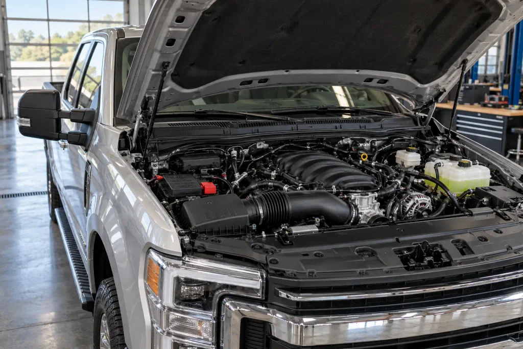
An under-hood service diagram is different from a bare-engine diagram. Several components you can reach when you open the hood, such as the battery and brake-fluid reservoir, are mounted around the engine rather than on the engine itself.
Ford identifies the following items as A through I in the 2026 Super Duty 7.3L gasoline under-hood overview:
| Ford Label | Under-Hood Component | What to Identify |
|---|---|---|
| A | Under-hood fuse box | Engine-compartment electrical fuse enclosure |
| B | Battery | Vehicle’s 12-volt battery |
| C | Engine oil dipstick | Oil-level checking point |
| D | Engine oil filler cap | Oil-fill opening |
| E | Brake fluid reservoir | Brake hydraulic-fluid container |
| F | Windshield washer fluid reservoir | Washer-fluid fill point |
| G | Engine coolant reservoir | Coolant expansion reservoir |
| H | Power steering fluid reservoir | Hydraulic steering-fluid container |
| I | Air cleaner assembly | Engine intake-air filter housing |
These are Ford’s callout identifiers, not measurements or a left-to-right sequence. Consult the official 2026 Ford Super Duty under-hood diagram to match each letter to its exact position in the truck.
For the oil quantity and service requirements after locating the dipstick and filler cap, use the dedicated Ford 7.3 gas oil capacity and maintenance specifications guide instead of relying on an engine illustration to determine fill volume.
Which Parts Make Up the 7.3 Godzilla V8
The Godzilla uses a cast-iron engine block and aluminum cylinder heads. Ford’s 2024 Super Duty crate-engine specifications also identify a forged-steel crankshaft, cast-aluminum pistons, port fuel injection, and a cam-in-block overhead-valve design with variable cam timing.
| Internal Part | Function |
|---|---|
| Cylinder block | Houses the eight cylinders and supports the crankshaft and camshaft |
| Pistons | Move within the cylinder bores as combustion pressure acts on them |
| Connecting rods | Transfer piston movement to the crankshaft |
| Crankshaft | Converts the pistons’ movement into rotary output |
| Camshaft | Operates the valve gear through lifters and pushrods |
| Valve tappets and pushrods | Carry camshaft movement toward the rocker arms |
| Rocker arms | Transfer pushrod motion to the valves |
| Intake and exhaust valves | Control the movement of air and exhaust gases |
| Timing chain and sprockets | Coordinate crankshaft and camshaft rotation |
| Oil pump | Circulates lubricating oil through the engine |
A cutaway drawing should show the crankshaft below the camshaft and the pushrod valvetrain extending upward toward both cylinder heads. It should not depict overhead camshafts in each head. That would represent a different Ford V8 architecture.
Ford lists a 107.2 mm bore and 101.0 mm stroke for the referenced 2024 crate engine. Those values explain the engine’s basic cylinder dimensions, not a location you can identify from outside the block.
How Does the Godzilla Camshaft and Valvetrain Work
The Godzilla’s single camshaft sits in the engine block. As the crankshaft turns, the timing chain drives the camshaft. The cam lobes act through valve tappets, pushrods, and rocker arms to open the intake and exhaust valves in the heads.
The basic movement path is:
Crankshaft → timing chain and sprockets → in-block camshaft → tappets → pushrods → rocker arms → valves.
Variable cam timing changes the camshaft’s phase relative to the crankshaft. It does not mean the engine has separate intake and exhaust camshafts mounted in the cylinder heads. The engine’s pushrod layout is one of the main details a correct Godzilla cutaway must preserve.


If you are studying the layout because of a tapping noise or persistent misfire, those symptoms need diagnosis rather than an assumed parts replacement. The separate Ford 7.3 Godzilla problems and diagnostic guide covers the relevant symptoms and Ford service-bulletin context without duplicating that repair discussion here.
Where Are Key 7.3 Godzilla Engine Sensors
An engine’s sensors are easier to identify when you first understand what each one measures. A connector’s appearance alone is not a reliable basis for labeling a sensor, especially when you are comparing photographs from different installations.
| Sensor or Input | Job in Engine Management | Identification Caution |
|---|---|---|
| Crankshaft position sensor | Supplies crankshaft speed and position information | Use the model-specific sensor and harness view |
| Camshaft position sensor | Supplies camshaft position information | Do not confuse it with the crankshaft sensor |
| Engine coolant temperature sensor | Monitors engine coolant temperature | Trace the correct coolant-system connection |
| Intake air sensing | Provides information about intake-air conditions | Sensor arrangement depends on the installed intake system |
| Engine oil pressure sensing | Monitors an aspect of engine oil pressure | Confirm the exact sender or control component before service |
Do not use the sensor-location drawing for a 7.3 Power Stroke diesel. Its injection-control sensors and high-pressure oil system are not the Godzilla gasoline engine’s setup. Exact Godzilla sensor positions and connector IDs should be taken from Ford workshop information for the specific model year and application, rather than guessed from a generic engine photograph.
How to Read 7.3 Godzilla Cylinder Numbering
The Ford 7.3L gasoline V8 uses a firing order of 1-5-4-8-6-3-7-2. Ford confirms that sequence in its 2026 Super Duty 7.3L engine specifications.
Cylinder numbering is different from firing order. The gasoline Godzilla identifies cylinders 1–4 on the passenger-side bank and 5–8 on the driver-side bank, progressing from the front of the engine toward the firewall.
                  FRONT OF TRUCK / RADIATOR

         PASSENGER SIDE            DRIVER SIDE
              BANK 1                 BANK 2

                1                      5
                2                      6
                3                      7
                4                      8

                   REAR / FIREWALL

          FIRING ORDER: 1-5-4-8-6-3-7-2
This reference is viewed in the direction of the installed engine, with the radiator at the front. If you stand in front of the grille looking toward the windshield, the passenger-side bank appears on your left. That reversal is a common source of cylinder-identification mistakes.
The older 7.3L Power Stroke diesel uses different cylinder numbering and a different firing order. Its diagram cannot be substituted when interpreting a Godzilla misfire code or ignition-wire location.
Which 7.3 Godzilla Drive Belt Layout Fits
The correct accessory-belt diagram depends on the installed generator configuration. Ford provides separate 7.3L gasoline routing illustrations for trucks equipped with a single generator and trucks equipped with dual generators.
Ford’s diagrams may identify two different belt planes: the drivebelt closest to the engine and the drivebelt furthest from the engine. Those descriptions refer to each belt’s fore-aft position, not to the left or right cylinder bank.
Before using a belt-routing drawing, verify the model year, count the installed generators, and match the pulleys and belt positions to the truck in front of you. The 2026 Ford single-generator drive-belt reference is specifically labeled for that equipment configuration; use the corresponding dual-generator illustration in the proper owner’s manual when your truck has two generators.
A simplified engine cutaway is useful for understanding the camshaft, but it is not a safe replacement for a factory belt-routing drawing during belt installation.
What Changes Across 7.3 Godzilla Applications
The base engine architecture remains recognizable, but a complete engine assembly, an installed engine bay, and a crate-engine or swap installation are not interchangeable diagrams.
A Super Duty under-hood drawing includes items such as the battery, fuse box, and coolant reservoir. A crate-engine product photograph may show the intake manifold, exhaust manifolds, oil pan, ignition components, and flexplate without the truck’s air-filter box or surrounding vehicle hardware.
Similarly, E-Series and medium-duty commercial applications can package their cooling, accessories, and service points differently. Even an official Ford engine specification should be read with its listed application and model year. For example, the 2024 Super Duty crate-engine listing gives 10.5:1 compression, but that specification should not be copied blindly into a description of every version or modified engine.
Identify which type of drawing you need before interpreting any small component as a universal location.
How to Match Your Engine to the Diagram
Use three quick checks before relying on a Godzilla diagram for maintenance or troubleshooting.
- Confirm the engine family. Verify that your truck has the 7.3L gasoline V8 rather than a 7.3L diesel, 6.8L gasoline V8, or another Ford powertrain.
- Match the model year and application. Select documentation for the installed Super Duty, E-Series, commercial chassis, or crate-engine configuration. A bare-engine illustration will not locate every under-hood service item.
- Check orientation and equipment. Confirm the front of the engine, passenger-side and driver-side banks, and single- versus dual-generator arrangement before following cylinder labels or belt routing.
If your next task is lubrication service, compare the model-year manual with the broader Ford engine oil recommendation chart. A general diagram cannot verify the required oil specification for your exact truck.
Engine diagrams are identification references. For disassembly, electrical testing, sensor replacement, or internal timing work, use the correct Ford workshop procedure and verify part fitment by VIN.


What to Verify Before Using a Godzilla Diagram
A useful Ford 7.3 Godzilla engine diagram must show the right engine, a clearly marked viewing direction, and components that match the vehicle or engine assembly being discussed. The most important visual landmarks are the top-mounted intake, two cylinder banks, in-block camshaft layout, front timing drive, and bottom-mounted oil pan. The gasoline engine’s cylinder numbering and Ford’s specified firing order are also essential when identifying ignition-related components.
Start with the general labeled layout to understand the assembly. Move to the model-year-specific under-hood or drive-belt drawing when you need to find a service point or trace an accessory belt. Before ordering a sensor, moving ignition parts, or opening the engine, confirm the component and procedure against your truck’s VIN and Ford service information.
Ford 7.3 Godzilla Engine Diagram FAQs
Where Can I Find a Ford 7.3 Godzilla Engine Diagram
Use an engine assembly drawing for internal parts or a Ford Super Duty owner-manual under-hood overview for accessible service points. The simplified diagrams and component tables above explain the layout, while the appropriate factory manual supplies vehicle-specific positions.
What Is the Firing Order of the 7.3 Godzilla V8
The firing order is 1-5-4-8-6-3-7-2. This is the combustion sequence, not the physical front-to-back numbering of the cylinders; use the cylinder layout above to identify the correct bank and position.
Is the 7.3 Godzilla the Same as the 7.3 Power Stroke
No. The Godzilla is a modern gasoline V8 with spark ignition and port fuel injection, while the older Power Stroke is a turbocharged diesel with a different injection system. Their engine diagrams, cylinder layouts, and firing orders should not be mixed.
Does Every Ford 7.3 Godzilla Use the Same Belt Diagram
No. Ford publishes separate accessory-drive routing references for single-generator and dual-generator installations. Match the factory illustration to your truck’s generator count, model year, and actual pulley layout before removing or fitting a belt.
Where Can I Find the Internal Parts Diagram for a 7.3 Godzilla Engine
Use a 7.3L-specific Ford parts catalog or workshop reference to identify the block, timing drive, valvetrain, crankshaft, pistons, and lubrication components. An exterior engine-bay picture cannot show those hidden parts accurately, and a diesel cutaway is not a suitable substitute.