Ford 351 Windsor Torque Specs Chart for Engine Bolts and Sequences 2026

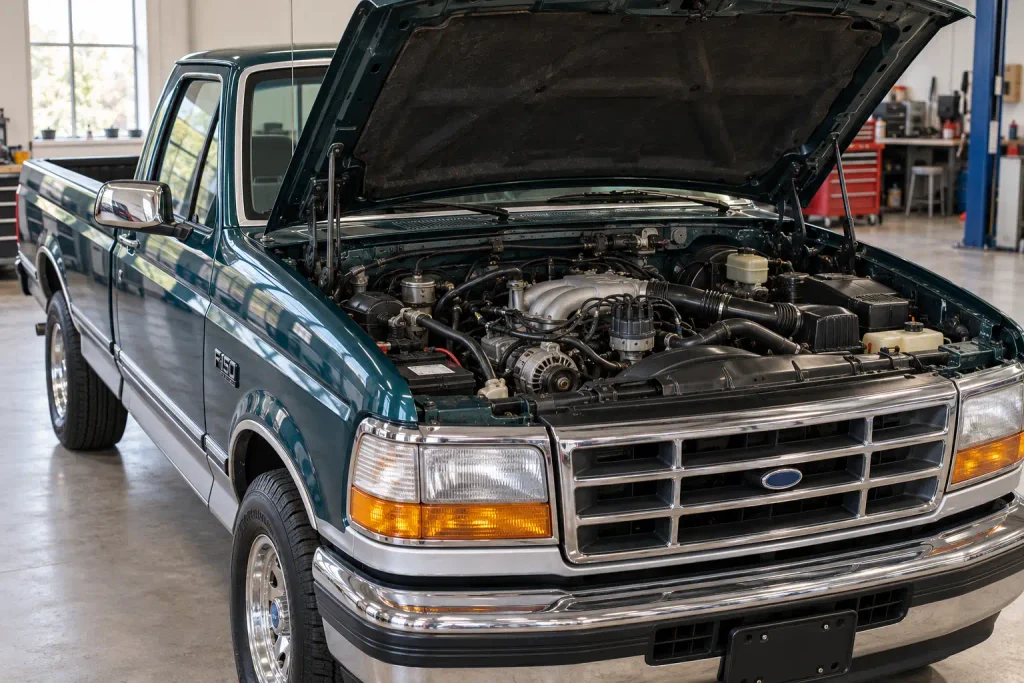
Ford 351 Windsor torque specs vary by fastener, engine year, and hardware. For a stock 1994 Ford F-150 5.8L Windsor, the published service chart lists 95–105 ft-lb for main bearing caps, 40–45 ft-lb for connecting rod caps, and 23–25 ft-lb for the intake manifold. Cylinder-head bolts require a separate tightening sequence and staged procedure.
Those numbers are not universal for every 351W rebuild. An original truck engine, aluminum-head conversion, and an engine fitted with ARP bolts can require different instructions. Use the application-labeled chart below as a reference, then verify the manual and hardware installed on your engine.
Ford 351 Windsor
Torque Specifications
5.8L V8 | Factory fastener values for the 1994 F-150 2WD reference application | All values in ft-lb
Three frequently checked fasteners
Factory Component Torque Chart
Service-manual values for a stock-style 1994 Ford F-150 5.8L engine. Not a universal specification for all 351W engines.
| Engine component | Torque (ft-lb) |
|---|---|
| Bottom end and rotating parts | |
| Main bearing caps | 95–105 |
| Connecting rod caps | 40–45 |
| Flywheel to crankshaft | 75–85 |
| Crankshaft damper | 70–90 |
| Camshaft sprocket bolt | 40–45 |
| Camshaft thrust plate | 9–12 |
| Intake, sealing and service hardware | |
| Factory intake manifold | 23–25 |
| Exhaust manifold | 18–24 |
| Oil pump retaining bolts | 22–32 |
| Oil pan bolts | 9–11 |
| Front engine cover | 12–18 |
| Water pump retaining bolts | 12–18 |
| Rocker arm fulcrum bolts | 18–24 |
| Spark plugs | 10–15 |
Reference: 1994 Ford F-150 2WD 5.8L service-manual torque list. Match year, hardware and thread treatment before assembly.
Cylinder Head Bolt Tightening
Different service reference: 1994 Ford F-250 5.8L. Complete the specified head-bolt sequence at every stage.
ARP head-bolt kit 154-3603 specifies 100 ft-lb in three equal steps with ARP Ultra-Torque, plus kit-specific thread and washer preparation. Do not apply the factory final torque to this kit.
How to Read Ford 351 Windsor Torque Specs Safely
Recommended Best Deal Products


The 351 Windsor is a 5.8-liter member of Ford’s small-block V8 family. Before picking up a torque wrench, identify the engine and the bolts you intend to tighten. A 351 Cleveland or 351M is not a 351 Windsor, despite sharing the 351-cubic-inch designation.
The Windsor has six valve-cover attaching bolts per head and its thermostat housing connects to the front of the intake manifold. The Cleveland uses a different cylinder-head and cooling-system layout. Confirm these identifying features before consulting a torque chart.
Next, establish whether you have factory cast-iron heads, aftermarket aluminum heads, original-style bolts, or a performance fastener kit. Record the vehicle year if the engine is original, or the engine’s actual build and parts specifications if it has been swapped.
Units matter: ft-lb means pound-feet of tightening torque. It is not the same as in-lb. One ft-lb equals 12 in-lb; using the wrong scale on smaller bolts can cause damage.
Finally, identify whether the prescribed torque assumes clean dry threads, oil, assembly lubricant, or thread sealer. The torque number and the specified thread treatment belong together.
Ford 351 Windsor Torque Specs by Engine Component
The following values come from the 1994 Ford F-150 2WD, 5.8L V8 service-manual torque chart. They are a factory-style reference for that application, not an all-years chart or a specification for aftermarket fasteners.
| Engine Component | Torque Specification | Application Note |
|---|---|---|
| Cylinder head bolts | See staged procedure below | Separate head-bolt sequence required |
| Main bearing caps | 95–105 ft-lb | Production-style bottom-end hardware |
| Connecting rod caps | 40–45 ft-lb | Production-style rod fasteners |
| Intake manifold to heads | 23–25 ft-lb | Factory reference; aftermarket instructions may differ |
| Exhaust manifold | 18–24 ft-lb | Factory manifold hardware |
| Flywheel to crankshaft | 75–85 ft-lb | Flywheel attaching bolts |
| Crankshaft damper | 70–90 ft-lb | Damper-to-crankshaft attachment |
| Camshaft sprocket bolt | 40–45 ft-lb | Camshaft sprocket retainer |
| Camshaft thrust plate | 9–12 ft-lb | Thrust plate fasteners |
| Oil pump retaining bolts | 22–32 ft-lb | Oil pump to engine |
| Oil pickup to pump | 10–15 ft-lb | Pickup tube attachment |
| Oil pan bolts | 9–11 ft-lb | Original pan fasteners |
| Front engine cover | 12–18 ft-lb | Timing/front cover |
| Water pump retaining bolts | 12–18 ft-lb | Factory pump mounting hardware |
| Rocker arm fulcrum bolts | 18–24 ft-lb | Factory-style rocker arrangement |
| Spark plugs | 10–15 ft-lb | Factory cylinder heads and plug specification |
| Upper to lower intake | 12–18 ft-lb | Applicable two-piece intake assembly |
The underlying 1994 Ford 5.8L torque specification listing provides the reference values and additional accessory fasteners.
Do not interpret the middle of a torque range as an automatic setting for a different model year. In particular, rod bolts, main studs, cylinder-head hardware, and aftermarket rocker systems must follow their own documentation. A calibrated torque wrench is necessary, but it cannot correct a specification chosen for the wrong part.
How to Torque 351W Cylinder Head Bolts Correctly
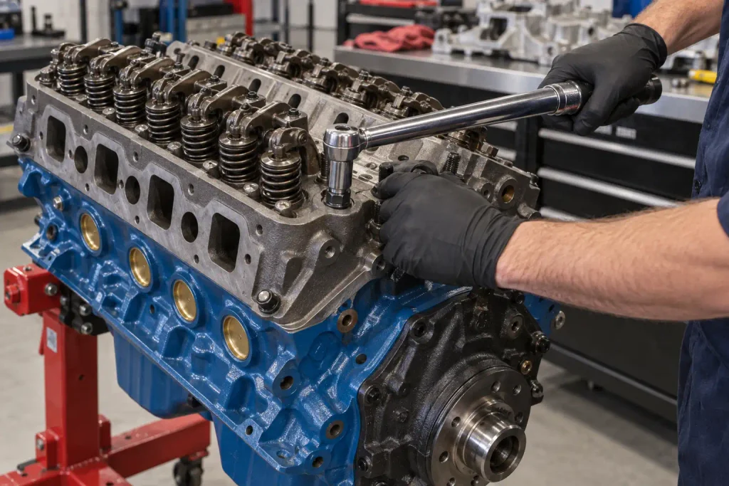
On the documented 1994 Ford F-250 5.8L Windsor application, the factory-style head installation procedure tightens the bolts in three complete passes:
- First pass: Tighten every head bolt in sequence to 85 ft-lb.
- Second pass: Repeat the full sequence at 95 ft-lb.
- Final pass: Repeat the full sequence at 105–112 ft-lb.
The 1994 Ford 5.8L cylinder-head service procedure specifies those stages. Follow the diagram and procedure for your exact engine where they differ.
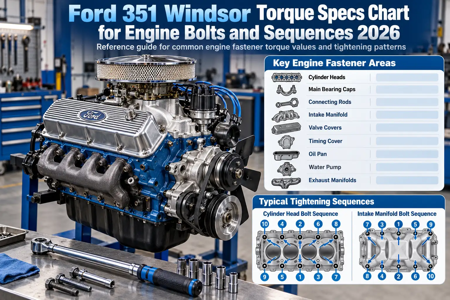
Head-bolt tightening order for one bank: A period Ford small-block service illustration shows ten fasteners arranged as follows when viewed from above, with the front of the engine to the right:
           FRONT OF ENGINE →

Upper row:   9    5    1    3    7
Lower row:  10    6    2    4    8
Complete positions 1 through 10 at each torque stage before increasing the wrench setting. The sequence distributes clamping load from the center toward the ends. Use the correct orientation for the head you are installing rather than rotating a diagram without checking it.
The bolt-tightening pattern is not the ignition firing order. If you also removed the distributor or spark-plug wires, check the 351 Windsor firing order and cylinder diagram separately.
Clean the bolt holes and gasket surfaces before installation. Inspect the bolts and confirm the replacement gasket and fasteners are appropriate for the engine. Apply only the thread treatment prescribed by the relevant service or bolt instructions, especially where a hole communicates with coolant.
This procedure is not the installation specification for ARP studs, aluminum aftermarket heads, or every earlier 351W. Their clamping requirements may differ.
How 351W Intake Manifold Torque Varies by Head Material
A stock 1994 Ford 5.8L intake manifold and a performance intake installed on aluminum heads should not automatically receive the same torque. The factory chart lists 23–25 ft-lb, while a Ford Racing 302/351W performance-manifold instruction sheet distinguishes between head materials.
For the intake covered by that Ford Racing sheet, install all 12 manifold bolts and tighten them in the specified pattern:
- Tighten all 12 bolts to 10 ft-lb in sequence.
- With aluminum heads, repeat the sequence to 18 ft-lb.
- With iron heads, use the same sequence to a final 22–24 ft-lb.
- Repeat the final pattern as instructed until all bolts hold their specified torque.
The Ford Racing 302/351W intake installation instructions also call for correct gasket fit, manifold clearance, washers, and approximately 5/8-inch thread engagement in the application described. Check these details before applying torque.
Ford Racing 12-bolt intake sequence, viewed from above with the front of the engine to the left:
← FRONT OF ENGINE

Upper row:  5    1    9   11    3    7
Lower row:  6    4   12   10    2    8
Other manifolds have their own requirements. For example, Edelbrock’s instructions for 351W Performer and Performer RPM intake models 2181, 3781, 3783, 7181, and 7581 specify 18–20 ft-lb in two stages. That figure applies to those manifolds and their documented installation conditions, not to every 351W intake.
Use the instructions supplied with your particular manifold and cylinder heads. A mismatched gasket, bolt length, or sealant procedure can cause trouble even if the wrench reaches the intended value.
How 351W Main and Rod Bolt Torque Differs
The factory 1994 351W bottom-end reference calls for 95–105 ft-lb on main bearing caps but only 40–45 ft-lb on connecting rod caps. These joints perform different jobs and use different fasteners. Swapping their torque values is not a minor adjustment.
Main bearing caps support the crankshaft in the block. During assembly, keep each main cap in its original position and orientation. Confirm that the bearing shells, journals, and fasteners match the rebuild plan, then tighten using the applicable factory or aftermarket procedure.
Connecting rod caps belong to their matched rods. The factory 40–45 ft-lb reference is not a substitute for a specification supplied with replacement rods or high-performance rod bolts. Some aftermarket rod fasteners use bolt-stretch measurement as the preferred assembly method.
Torque alone cannot confirm correct bearing clearance. Measure the crankshaft and bearing clearances according to your engine-building specifications and check crankshaft rotation as assembly progresses. If the crank binds or measured clearances are wrong, investigate before continuing.
For a visual identification of the crankshaft, heads, and other related parts, consult our Ford 351 Windsor engine diagram.
When ARP Head Bolts Change 351W Torque Values
An aftermarket cylinder-head bolt kit can change the torque number as well as the required lubricant. ARP kit 154-3603, intended for the 351W, calls for 100 ft-lb in three equal steps with ARP Ultra-Torque assembly lubricant. Do not substitute the stock 105–112 ft-lb final range for this particular kit.
The ARP 154-3603 installation sheet also requires careful thread cleaning and inspection. Its washer must sit with the chamfer facing the bolt head, while the underside of the bolt head and the washer receive the specified assembly lubricant.
For bolt holes that enter a water jacket, ARP directs the installer to use its thread sealer on the threads. For blind holes, the sheet specifies ARP Ultra-Torque on the threads. That difference matters because thread treatment changes friction and helps control the intended clamp load.
The 100 ft-lb figure is kit-specific. It does not automatically apply to another ARP kit, stud set, cylinder head design, or lubricant. Check the part number stamped on the package and the latest instructions shipped with the hardware before installation.
5 Torque Mistakes That Damage a 351 Windsor
A dependable 351W rebuild starts by avoiding a few preventable fastener errors.
- Using 302 head or main-cap values. Both engines belong to the Windsor family, but their fastener specifications are not interchangeable. Our Ford 302 torque specs chart covers that smaller engine separately.
- Confusing the Windsor with another 351. Confirm the engine family before using a chart. A Cleveland or 351M manual is not the reference for a 351W block.
- Tightening one head bolt fully before the others. Complete every numbered pass before moving to the next stage so clamping load builds in the specified order.
- Changing lubricant without checking the torque procedure. A fastener tightened with oil, thread sealer, or assembly lube may develop a different clamp load at the same wrench reading. Follow the hardware maker’s instructions.
- Ignoring aftermarket part instructions. An aluminum-head conversion, performance intake, or rod-bolt kit may override the factory-style values for that component.
A wrench clicking at the selected torque only shows that the set torque was reached. It does not confirm that the bolt, lubricant, gasket, or specification is correct.
How to Confirm 351W Torque Before Assembly
Use these four checks before the final tightening pass:
- Identify the engine. Confirm it is a Windsor 5.8L, and note its year and original application or documented rebuild specifications.
- Identify the hardware. Check stock versus aftermarket heads, rods, intake manifold, bolts, and studs. Record any kit part numbers.
- Match the instructions. Compare the year-specific Ford service procedure with the documentation for replacement parts. Where an aftermarket instruction specifically covers the installed component, follow it for that hardware.
- Prepare and verify. Check thread condition, lubricant or sealer, wrench calibration, bolt sequence, and units before starting each pass.
Stop if you cannot identify the fastener or find an applicable instruction. Confirm the specification with the component manufacturer or a qualified engine builder rather than selecting a convenient number from a generic chart.
Which 351W Torque Values Should You Use
The correct Ford 351 Windsor torque specs begin with the engine and hardware you actually have. For a stock 1994 5.8L truck-engine reference, main caps are listed at 95–105 ft-lb, rod caps at 40–45 ft-lb, and the intake manifold at 23–25 ft-lb. Cylinder heads require their own sequence and tightening stages.
Those baseline numbers do not override instructions supplied with ARP hardware, performance intake manifolds, or aftermarket cylinder heads. A precise torque reading on the wrong specification still creates an assembly risk.
Before tightening any critical fastener, match the component, model-year service data, specified thread treatment, and tightening order. That verification is the most useful step you can take toward a reliable 351W assembly.
5 Common Ford 351 Windsor Torque Questions
What Are the Head Bolt Torque Specs for a 351 Windsor?
For the documented 1994 Ford 5.8L truck procedure, the three stages are 85 ft-lb, 95 ft-lb, and a final 105–112 ft-lb, each performed in the proper sequence. Different fastener kits and some other service applications require their own instructions.
What Is the Torque for a 351W Intake Manifold?
The 1994 factory-style intake reference lists 23–25 ft-lb. The specified Ford Racing performance-manifold procedure calls for 18 ft-lb with aluminum heads or 22–24 ft-lb with iron heads after an initial 10 ft-lb pass. Follow the instructions for the intake actually installed.
How Tight Should 351W Main Bearing Caps Be?
The 1994 Ford 5.8L service reference lists 95–105 ft-lb for production-style main bearing caps. Aftermarket main bolts or studs may have different requirements, so verify the installed hardware before tightening.
Are 302 and 351 Windsor Torque Specs the Same?
No. The two engines share a small-block family background, but important fasteners, including head and main-bearing hardware, have different specifications. Use a 351W-specific manual rather than copying numbers from a 302 chart.
Do ARP Head Bolts Need Different Torque Specs?
Often, yes. ARP’s 351W head bolt kit 154-3603 specifies 100 ft-lb with ARP Ultra-Torque in three equal steps, along with particular washer and thread-treatment instructions. Another ARP kit may require a different value, so verify the actual kit number.