
Ford Factory Amplifier Subwoofer Wiring Diagram: Full Pinout

Ford does not use one factory amplifier and subwoofer wiring diagram. Trucks and SUVs built from 2009 to 2017 with the Sony system use a Blue 16-pin subwoofer connector. They pair it with a separate Gray 16-pin speaker connector.
The 2018-2020 B&O system uses a different 20-pin connector instead. Anything older is wired per model, with no shared chart at all.


2011 and 2013 F-150 owners should check the amplifier fuse first. This site’s 2011 Ford F-150 fuse box diagram or 2013 Ford F-150 fuse box diagram shows which one.
Below is the full pinout for every system Ford used. The symptom-to-fix table readers ask for most is further down the page.
Most “Ford factory amplifier wiring diagram” pages show one chart for every Ford


Search that phrase and most results publish a single color table labeled simply “Ford.” That is wrong on its face. A 2005 F-150 and a 2013 F-150 share no connector, no pin count and no wire color.
Four independently documented systems exist. Pre-2009 trucks and SUVs each used a proprietary low-pin harness. It varies by model and even by radio trim.
The 2009 to roughly 2017 “Sony” system standardized on a Blue 16-pin subwoofer plug and a Gray 16-pin speaker plug. It spans F-150, Explorer, Expedition, Super Duty, Flex, Focus, Fusion, Taurus and the 2019-2023 Mustang. The 2018-2020 B&O system moved to one 20-pin Gray connector instead.


The Edge and Escape crossover platform runs yet another 18-pin layout with its own colors.
Worth knowing: two sources that agree a 16-pin Gray connector exists still disagree on which side it feeds. That disagreement is named, not hidden, further down this page.
Where is the factory amplifier?


On the Sony-amplified F-150, Explorer and Expedition, the amplifier sits under the center console or in the cargo area. It feeds the factory subwoofer enclosure right behind it. On a 2005 F-150, the amplifier and subwoofer sit in the driver’s side rear corner of the cab instead.
Edge owners get a mid-generation relocation. The amplifier sits behind the right C-pillar on 2011-2014 trucks, then moves behind the left quarter panel for 2015-2017. Confirm the location for your exact year before pulling trim panels.
2009-2017 Sony system: Blue 16-pin subwoofer connector


Three independent sources confirm this connector and pinout. They are PAC Audio’s APH-FD01 manual, that harness’s own application list, and matching forum reports from owners.


It covers F-150 2009-2017, Explorer 2011-2017, Expedition and Edge 2015-2017, and Super Duty 2013-2019. It also covers Flex 2009-2012, Focus 2012-2017, Fusion 2010-2016, Taurus 2010-2015 and the 2019-2023 Mustang. Ford specifies all of these as carrying the factory Sony amplifier.
| Pin | Circuit | Wire color | Note |
|---|---|---|---|
| 16 | Subwoofer 1 (+) | Black/White | Pairs with pin 8 |
| 8 | Subwoofer 1 (-) | Black | Pairs with pin 16 |
| 15 | Subwoofer 2 (+) | Black/Red | Pairs with pin 7 |
| 7 | Subwoofer 2 (-) | Black/Green | Pairs with pin 15 |
| 1, 2, 9, 10 | Pass-through, not subwoofer circuits | Black, Black, Yellow, Yellow | Leave these alone |
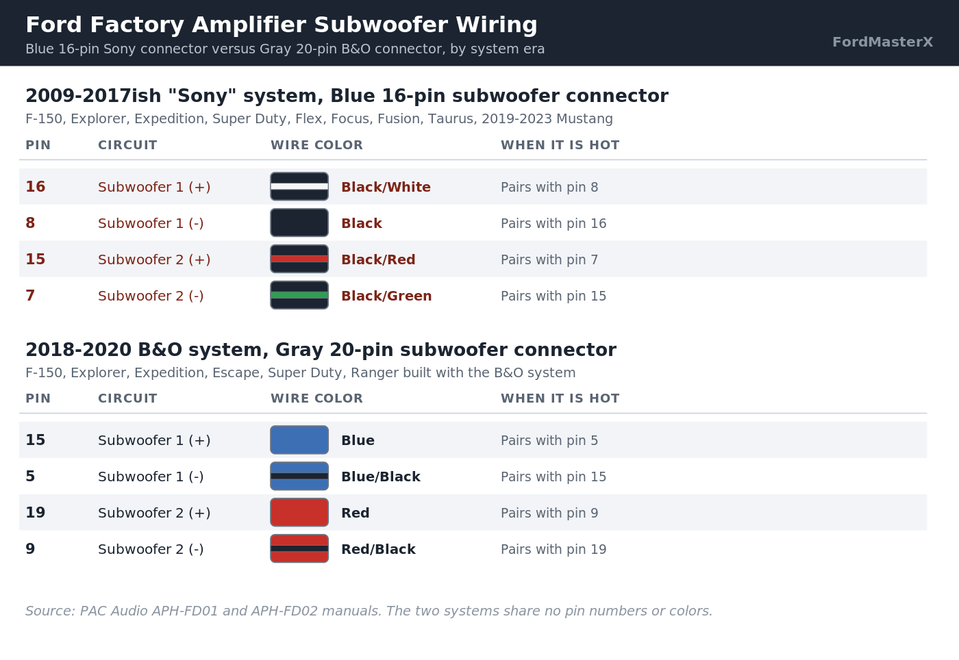
Both subwoofer channels carry one mono signal split across the dual voice coil factory subwoofer. It is not a true stereo pair.
If you are adding a line output converter, pick one rated for speaker-level input. A speaker-level line output converter handles this tap cleanly.


Our best speaker picks for the Ford F-150 cover replacements sized to fit the factory mounts.
2009-2017 Sony system: Gray 16-pin speaker connector
The same Blue-connector vehicles use a Gray 16-pin plug for all eight speaker channels. That includes the front tweeters and center channel. PAC Audio’s manual documents 47-ohm, 5-watt resistors built into this harness.
Those resistors keep the factory warning chimes playing through the door speakers once an aftermarket amplifier goes in.
| Pin | Circuit | Wire color |
|---|---|---|
| 9 / 1 | Right Rear Speaker (+/-) | Purple / Purple-Black |
| 10 / 2 | Right Front Tweeter (+/-) | Gray/Red / Gray-Blue |
| 11 / 3 | Right Front Speaker (+/-) | Gray / Gray-Black |
| 12 / 4 | Rear Center Speaker (+/-) | Black/White / Black |
| 13 / 5 | Left Rear Speaker (+/-) | Green / Green-Black |
| 14 / 6 | Left Front Tweeter (+/-) | White/Red / White-Blue |
| 15 / 7 | Left Front Speaker (+/-) | White / White-Black |
| 16 / 8 | Front Center Speaker (+/-) | Brown / Brown-Black |
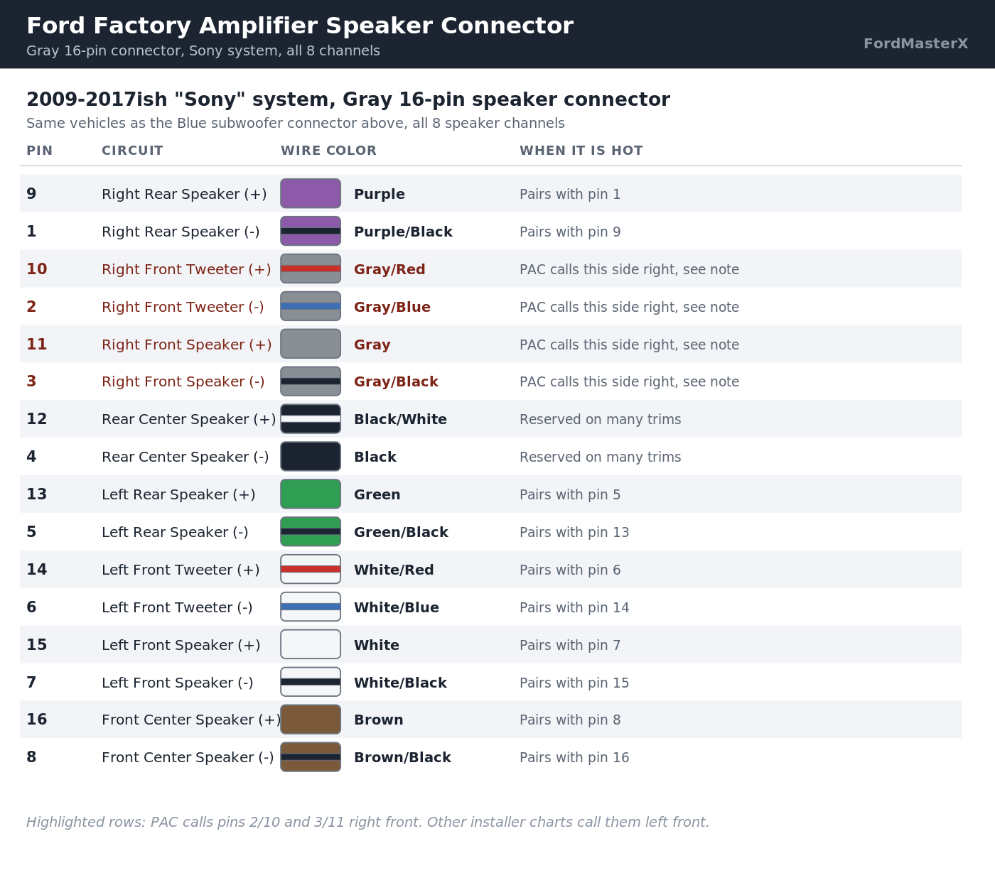
Here is the disagreement, named up front. PAC’s own manual calls pins 2/10 and 3/11 the right front channel. Three separate installer charts disagree, reposted across forum threads for a 2014 F-150, a 2012 Focus and a 2020 Fusion.
All three call the same two pin pairs the left front channel instead, with different wire colors entirely. Both sides agree the connector and pin numbers exist on all three vehicles. They disagree on which side of the truck those pins feed.
Trust PAC’s manual if you are using a PAC adapter. Its pins have to match the physical harness it sells. Either way, confirm left versus right with a multimeter against your own door speaker first.
2018-2020 B&O system: Gray 20-pin connector
Ford’s 2018-2020 F-150, Explorer, Expedition, Escape, Super Duty and Ranger with the B&O system use one 20-pin Gray connector. That replaces the older two-connector Sony layout entirely. Two independent retailer listings for the PAC APH-FD02 harness confirm the same vehicle range.
| Pin | Circuit | Wire color |
|---|---|---|
| 15 / 5 | Subwoofer 1 (+/-) | Blue / Blue-Black |
| 19 / 9 | Subwoofer 2 (+/-) | Red / Red-Black |
| 16 / 6 | Right Front Speaker (+/-) | Gray / Gray-Black |
| 17 / 7 | Left Front Speaker (+/-) | White / White-Black |
| 18 / 8 | Right Rear Speaker (+/-) | Purple / Purple-Black |
| 20 / 10 | Left Rear Speaker (+/-) | Green / Green-Black |
| 14 / 4 | Center Channel (+/-) | Brown / Brown-Black |
| 1 / 11 | CAN bus (+/-) | Pink / Pink-Black |
None of these colors or pin numbers carry over from the Sony system above. If your build sheet lists B&O audio, use this table instead. Do not use the Blue/Gray 16-pin tables, even on the same model year.
Before 2009: expect no shared chart at all
A 2005 F-150 taps its factory subwoofer at the radio on Brown/Orange positive and Red/Black negative. Its amplifier turn-on wire is dark Green/Purple. An installer forum thread for that exact truck confirms all three colors.
A 2006 Explorer with the Premium/Audiophile system uses a completely different 10-pin, 5-wire harness. The subwoofer signal runs on Purple/green stripe and Green/white stripe. Ground is Black/blue, and constant power is Grey/red.
Neither harness resembles the Sony or B&O connectors above, and the two trucks do not resemble each other. One owner on the Explorer thread searched for months and never found a published diagram. Treat any pre-2009 wiring claim as unverified until you check it yourself.
How to tap the factory subwoofer output for an aftermarket amp
This applies once you have matched your truck to the correct connector above.
First, confirm the connector family against your build sheet or by sight. The wrong table sends current into the wrong circuit. Second, disconnect the factory amplifier and test each candidate pin with a multimeter, key on, before cutting anything.
Third, treat the two subwoofer pins as one mono pair, not left and right. Wiring a second amplifier to both the factory sub output and a new speaker-level tap at once just fights itself.
Fourth, keep the factory speaker pass-through wiring intact if you want chimes to keep working. Removing the resistor-equipped harness without a replacement sends the chimes to a small piezo speaker in the dash instead.
Why won’t my aftermarket amp turn on with the factory harness?
Ford’s factory amplifier turn-on lead is a 4 to 5 volt logic signal, not switched 12 volts. Most aftermarket amplifiers need a true 12 volt signal to trip their own turn-on relay. Wiring the factory lead straight to the amp’s remote input often does nothing.
The fix is a remote turn-on trigger module. Wire it between a constant 12 volt source, a ground, and the factory low-voltage lead as its trigger input.
One documented installer went through a defective trigger module first. Test the new module’s output voltage before you blame the truck’s wiring again.
Ford factory amp and subwoofer symptom to fix guide
Readers usually arrive with a symptom, not a pin number. This maps the common ones.
| What is happening | Check this first |
|---|---|
| No sound anywhere, radio display is also dead | Main radio fuse, not the amplifier circuit |
| Radio and display work, no sound from any speaker | The dedicated amplifier fuse on your platform, see below |
| Door speakers play fine, no bass at all | Subwoofer voice coil continuity, then the amp’s sub channel |
| Bass present but weak or muddy | Reversed polarity on one subwoofer tap |
| Aftermarket amp installed, will not power on | The 4-5V factory trigger signal, see the turn-on section above |
| Chimes went silent after an amp swap | Missing resistor-equipped pass-through pins on the speaker harness |
| Sound cuts in and out intermittently | A loose factory amplifier connector pin before you replace the amp |
The amplifier fuse itself is not standardized either. On the 2011 and 2013 F-150, fuse 19 (20A) feeds the audio amplifier on its own circuit. Losing sound while the display stays lit points there first.
On a 2002 Ford Explorer, one shared fuse covers the radio, amplifier, power antenna and DVD system together. A blown fuse 3 (20A) takes out all four at once, a different symptom from the same kind of failure. Check our 2002 Ford Explorer fuse box diagram if that is your truck.
If the amplifier checks out and the problem sits upstream of it, stop swapping parts on a guess. A proper OBD2 scanner finds a dropped module signal a multimeter alone will miss.
Factory amplifier connector quick reference
The rows readers look up most, in one place.
| System | Years / vehicles | Subwoofer connector |
|---|---|---|
| Sony amplified | F-150, Explorer, Expedition, Super Duty, Flex, Focus, Fusion, Taurus, Mustang (2009-2017ish) | Blue 16-pin, pins 16/8 and 15/7 |
| B&O amplified | F-150, Explorer, Expedition, Escape, Super Duty, Ranger (2018-2020) | Gray 20-pin, pins 15/5 and 19/9 |
| Edge/Escape crossover | Edge 2011-2018 | 18-pin, colors specific to this platform only |
| Pre-2009 | Varies by model and trim | No shared chart, confirm by hand every time |
Match your truck’s year and audio brand to one row first. A Sony-system chart applied to a B&O truck puts current into the wrong circuit. Both trucks can look identical from the driver’s seat.
Confirm every pin with a multimeter before you cut, splice or connect anything. None of these tables replace a continuity check on your own exact truck.


