
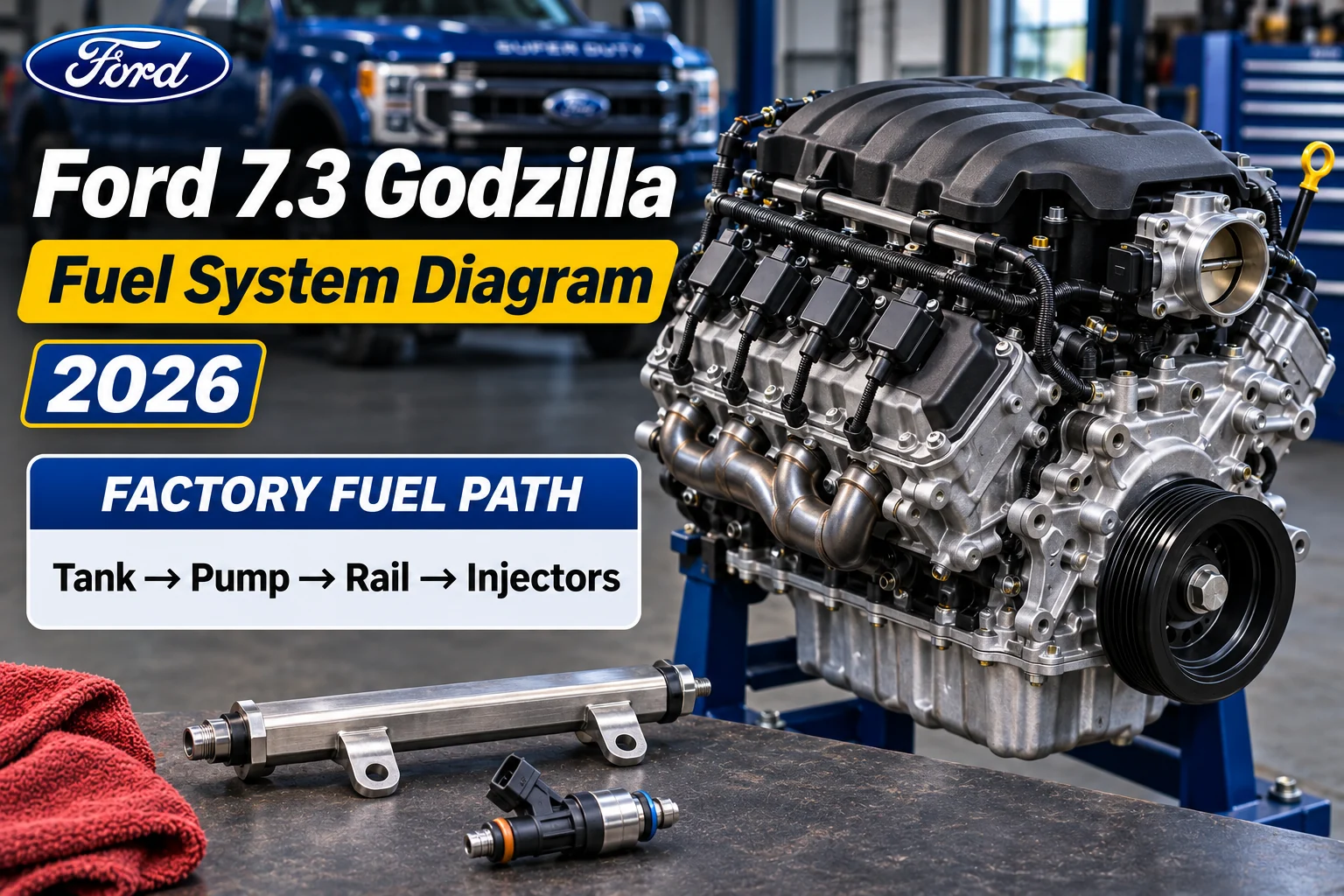
Ford 7.3 Godzilla Fuel System Diagram 2026 | Essential Guide

In the documented 2020 Ford F-350 7.3L gasoline application, fuel travels from the in-tank pump module through a supply line to the fuel rail and port injectors. The powertrain control module, or PCM, requests pump output through a separate fuel pump control module. Ford describes this stock application as a two-speed mechanical returnless fuel system. The vapor line belongs to the evaporative emissions system.
The diagram below separates the liquid fuel path, the pump-control signal and the vapor circuit. It is based on the 2020 F-350 Super Duty XL cab-and-chassis workshop entry for engine VIN code N. Check the service information for your own model, year and tank configuration before using this guide to identify a connector or order a part.

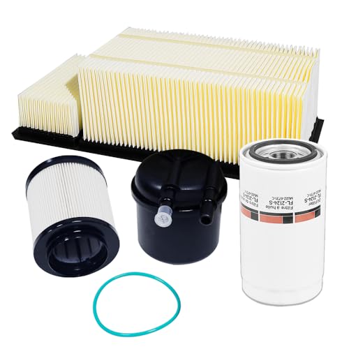

Ford 7.3 Godzilla fuel system diagram
Fuel tank → In-tank pump and filter module → Supply line → Fuel rails → Port injectors → Intake ports
PCM request → Fuel pump control module → In-tank pump output
Tank vapor connection → EVAP plumbing
Functional schematic. Verify exact component locations and connectors for the vehicle. Ford Performance crate control-pack instructions may call for a return-style system.
Liquid fuel path: Fuel tank → in-tank pump and filter module → supply line → fuel rail → port injectors → intake ports.
Pump control path: PCM → fuel pump control module → pump output.
Vapor path: Fuel tank vapor connection → evaporative emissions plumbing. During commanded purge, the system can route stored vapor to the intake.
The arrows show the function of each circuit. Use the applicable Ford component-location illustration for the physical routing under the truck. The 2020 F-350 7.3L Ford workshop fuel system overview identifies the stock pump, integral filter, fuel tubes, vapor tubes and pump-control strategy. Ford’s 7.3L V8 engine specification sheet identifies port fuel injection for the gasoline engine.
Follow the fuel from the tank to the intake ports

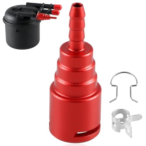

Fuel tank and in-tank pump module
The tank is the starting point for the liquid fuel path. In the documented application, the electric fuel pump is part of a module inside the tank. Ford lists the fuel filter as part of that module. If a parts diagram shows the filter with the pump assembly, check how the filter is serviced before searching for an external replacement.
The tank and module can vary with the truck’s body and fuel tank options. When looking up the module, use the VIN and confirm the actual tank installation. A wiring connector that resembles another truck’s connector does not establish that the two pump modules fit the same tank or use the same control strategy.
Fuel supply line


The supply line carries pressurized liquid fuel from the tank assembly toward the engine. It is one of the lines you may see along the chassis. Ford lists separate fuel and vapor tubes, so lines that travel alongside one another can serve different functions.
Start identification at a known endpoint in the Ford drawing. At the tank, distinguish the liquid outlet from the vapor connection. At the engine, the liquid supply terminates at the fuel rail assembly. A disconnected or unlabeled line deserves a check against the vehicle-specific diagram before it is moved or reused.
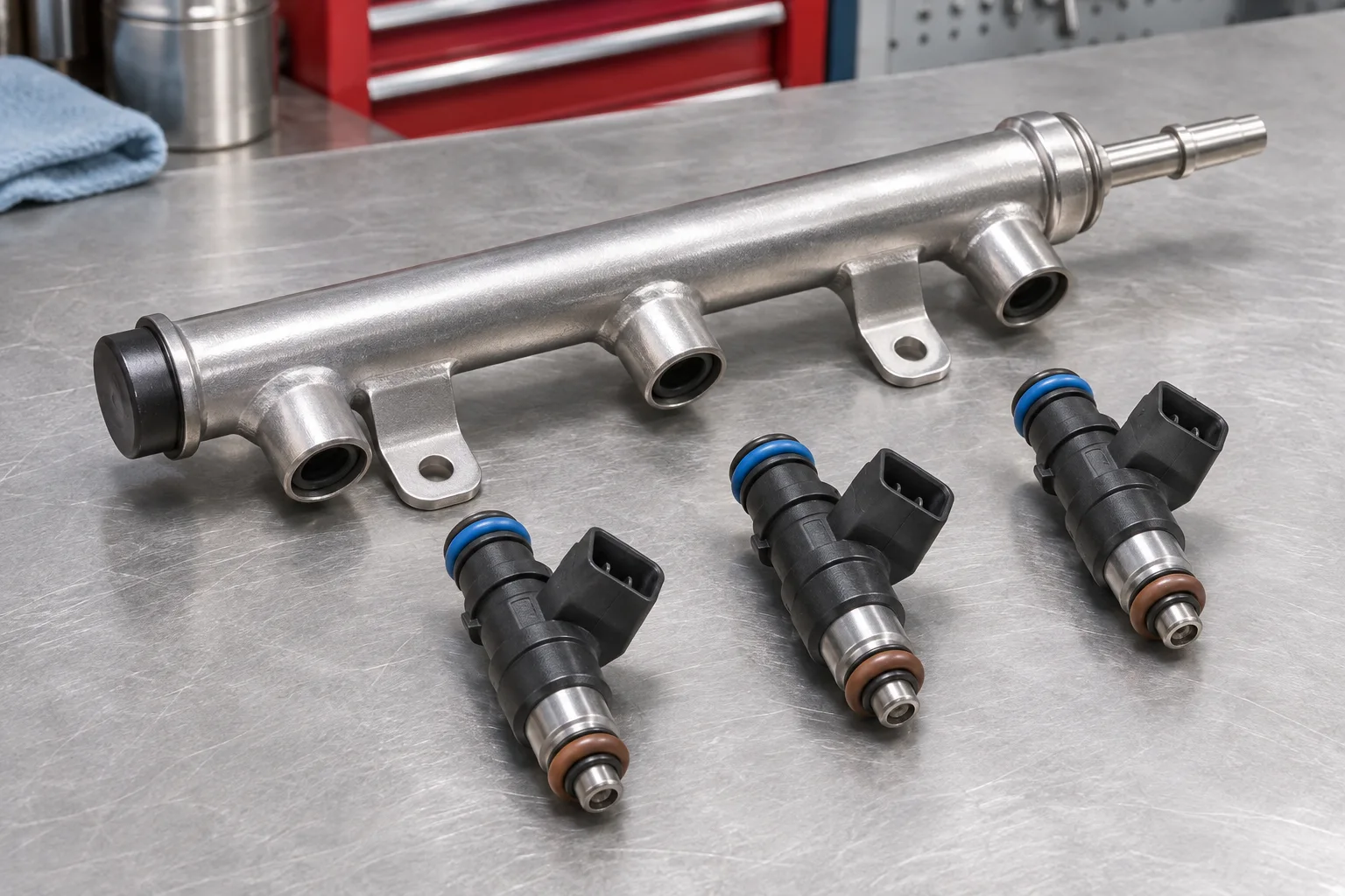
Fuel rail and port injectors
The rail distributes fuel to the injectors. The Godzilla’s gasoline port injectors deliver fuel into the intake ports, where it mixes with incoming air before entering the cylinders. This layout explains why a direct-injection diagram showing a separate engine-driven high-pressure pump is a poor guide to identifying the stock Godzilla’s port-injection hardware.


Ford’s 2020 F-250 VIN N rail service entries show the incoming supply tube at the left-hand rail and a jumper between the two rails. Each rail serves its own bank of port injectors. Use the left- and right-hand drawings for that application if you need to identify the actual tube endpoints. The fuel rail is part of the engine-side distribution path. The pump module belongs to the tank-side supply path. An engine diagram is useful when locating the intake and nearby top-end components, while the fuel-system diagram traces the supply from the tank to those components. The Ford 7.3 Godzilla engine diagram gives additional orientation around the engine.


How the PCM and fuel pump control module work together


Ford describes the documented 2020 system as a two-speed mechanical returnless system supplying electronic multi-port injection. The PCM sends a duty-cycle request to the fuel pump control module. The control module changes the voltage supplied to the pump according to the request, and the pump delivers fuel to the rail.
The control signal is separate from the liquid path. The PCM does not sit in the supply line, and the fuel pump control module does not replace the pump. That distinction matters when a code or a wiring diagram mentions the control module. The named module and the component that physically moves the fuel are different points in the system.
Use the matching Ford wiring diagram and pinpoint test if you are diagnosing the circuit. Connector pins, module location, expected voltage and enable conditions can vary. Keep the wiring information with the correct truck record rather than transferring a connector diagram from another year or powertrain.


What returnless means on this truck


In the stock layout described here, the engine-side diagram shows a feed to the rail. There is no external fuel-return line running from an engine-bay regulator back to the tank in the documented production configuration. The tank-side arrangement and pump control are covered in the relevant Ford service information.
Returnless refers to the liquid fuel delivery arrangement. The tank still has a vapor path for evaporative emissions control. A line routed back toward the tank may belong to vapor management, so use the proper component and line labels before interpreting what you see under the truck.
Stock Super Duty versus a 7.3 Godzilla crate swap
| Question | Documented stock 2020 F-350 7.3L | Ford Performance M-6017-73A control-pack example |
|---|---|---|
| Injection system | Gasoline port fuel injection | Godzilla port-injected engine with the specified control pack |
| Liquid line layout | Mechanical returnless fuel delivery | Return-style system required by the control-pack instructions |
| How to verify | Ford workshop information for the vehicle and tank configuration | The installation sheet for the exact control pack and revision |
| What a pressure figure applies to | The factory diagnostic procedure for that truck | The stated pump capacity and pressure requirement of the kit |
Ford Performance’s M-6017-73A V5 installation instructions specify a return-style fuel system for that calibration. The instructions list a minimum pump capacity of 160 L/h at 60 psi for the kit. That is a control-pack specification. Use the factory workshop diagnostic information to determine the stock truck’s relevant test conditions and acceptable pressure.
If you are looking at a swapped vehicle, identify the control pack, pump arrangement and installed regulator before drawing conclusions from the plumbing. An aftermarket controller or a different kit may call for a different design. The same 7.3L engine can appear with different fuel delivery hardware depending on whether it is in a production Super Duty or a custom installation.
Keep the two diagrams with their source names when comparing parts. A return-style schematic can help explain a particular control-pack installation. A stock returnless schematic helps locate the production truck’s parts. Identify which system you have before comparing a pressure figure, wiring pin or connection.
Factory fuel pressure versus the crate-kit figure
Ford’s 2020 F-250 7.3L VIN N workshop pressure specification gives 50.8–62.4 psi (350–430 kPa) for the key-on, engine-running test. This is a documented stock example for that model and test condition. Check the workshop information for the exact truck before interpreting a measurement on another application.
The 60 psi number in the Ford Performance V5 instructions is the pressure at which the pump must meet the minimum specified flow. Write down the vehicle or control pack and the test condition whenever you record pressure. A running specification and a pump-capacity rating describe different measurements, even when their numbers overlap.
Use the diagram to organize a fuel-delivery diagnosis
Cranks without starting
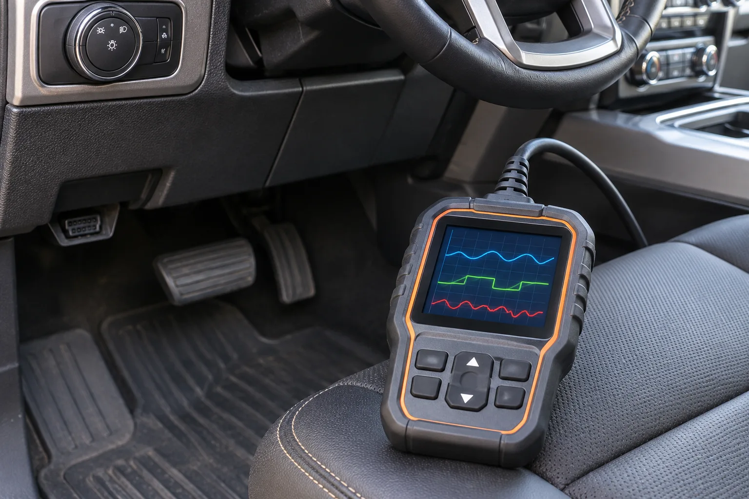
A crank-no-start can have more than one cause. If the service procedure directs you to investigate fuel delivery, identify whether the problem is on the command side, the pump circuit or the liquid supply path. Check for available diagnostic codes and freeze-frame data before deciding which component to test.
Use the vehicle-specific procedure for pressure measurement and circuit checks. A pump that can be heard briefly can still produce insufficient flow under a given test condition. A silent pump may also have an electrical supply or control issue. The diagram helps identify the relevant circuit, while the service test determines which observation supports a diagnosis.
Runs poorly under load


Record when the symptom occurs, including whether it is present at idle, during acceleration or under sustained load. A symptom that appears during a specific operating condition is easier to investigate when you can review the data recorded at that time. Check the Ford procedure for which values and operating conditions are meaningful for that truck.
Keep fuel-delivery checks alongside ignition and other engine diagnostics. A misfire can have several causes, and the fuel system diagram alone does not establish the reason. The Ford 7.3 Godzilla problems guide gives wider context for symptoms that can resemble a fuel-delivery issue.
Fuel odor or an evaporative emissions fault
A fuel odor may come from a liquid leak or a vapor-system fault. Stop operating the vehicle if you suspect liquid fuel is leaking and arrange qualified inspection. Keep ignition sources away from a suspected leak. Use the Ford procedure for safe inspection and pressure relief before opening any pressurized fuel connection.
For a vapor-related code, identify the tank vent plumbing, canister path and purge circuit using the correct vehicle diagram. Keep those components separate from the liquid supply and pump-control paths. A test aimed at one circuit can miss a fault in another circuit that is nearby on the chassis.
What to confirm before ordering a pump, injector or line
Start with the model year, VIN and body configuration, then match the existing system. Check whether the truck is stock, whether the tank has been replaced and whether the engine or wiring has been swapped. This information can narrow the parts choices faster than a search based only on the name Godzilla.
For a pump module, match the tank and the module’s service parts. For a line, confirm both endpoints and the application. For an injector, use the applicable Ford catalog and verify the engine and connector details. Part numbers from another Ford 7.3 application can look plausible even when the truck in front of you uses different hardware.
A useful repair record includes the symptom, the conditions in which it occurred, the observed codes and the reference used for the test. Record the actual component you checked and the result. This helps a later technician distinguish a suspected pump fault from a confirmed electrical or mechanical finding.
Ford 7.3 Godzilla fuel system FAQ
Does the Ford 7.3 Godzilla use direct injection?
Ford identifies the 7.3L gasoline V8 as port-injected in the cited engine specification. The factory service reference for the documented F-350 identifies multi-port injection. Use the vehicle-specific diagram when comparing the pump, rail or injectors for a particular truck.
Where is the fuel filter on the documented 2020 truck?
Ford’s 2020 F-350 workshop overview lists a lifetime filter serviced as part of the in-tank fuel pump module. Confirm the tank and exact application when ordering parts or checking the service procedure.
Does the stock 7.3L truck use an external fuel return line?
The cited 2020 F-350 system is mechanically returnless. The diagram shows a supply from the tank-side pump module to the fuel rail. A vapor line is present as part of the separate evaporative emissions system.
Is 60 psi the right number for my stock truck?
The Ford Performance M-6017-73A V5 instructions specify a minimum pump capacity of 160 L/h at 60 psi for the return-style control pack. The cited stock 2020 F-250 specification gives a running range of 50.8–62.4 psi. Use the test conditions and specification for your exact truck.
What diagram should I use on a crate-engine swap?
Start with the instructions for the exact control pack or controller on the vehicle and compare them with the installed tank, lines and regulator. Ford Performance specifies a return-style arrangement for the cited M-6017-73A example. The parts and instructions on a different swap may vary.
Match the diagram to the system you have
The Ford 7.3 Godzilla fuel system diagram starts with the tank, pump module and supply line, then reaches the fuel rail and port injectors. The PCM and pump control module belong to the electrical path. The EVAP tubing carries vapor. Identify the vehicle or control pack before applying a pressure figure, wiring test or replacement part number.