
Ford 6.8 V10 Torque Specs 2026 | Essential Guide

Ford 6.8 V10 spark plug torque depends on the engine and plug design. A documented 2-valve VIN S example specifies 11 lb-ft (15 N·m). Ford’s 3-valve table lists 25 lb-ft (34 N·m) for its early-build plug configuration and 9 lb-ft (12 N·m) for its late-build plug configuration. Identify the applicable plug and build before setting the wrench.
The 2004 2-valve and 2007 3-valve workshop examples below both specify 30 lb-ft (40 N·m), then 90°, then another 90° for new cylinder head bolts. The intake manifold is where inches and feet can be easy to confuse. One documented lower intake uses 18 lb-in followed by 89 lb-in, while a separately identified upper intake on the 2-valve example finishes at 18 lb-ft.


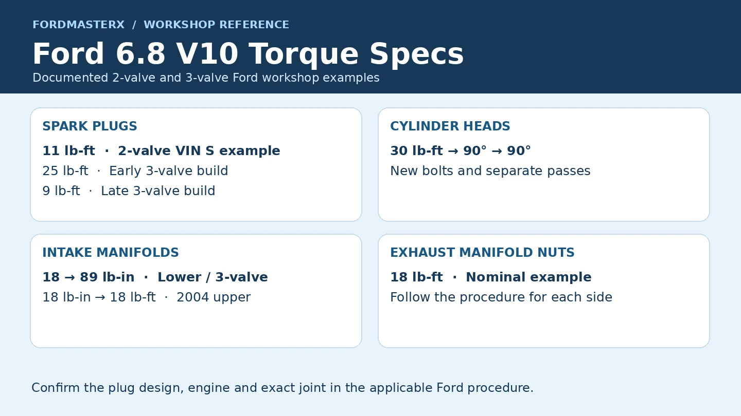
Ford 6.8 V10 torque chart by component
VIN S 2-valve example: 11 lb-ft
3-valve early build: 25 lb-ft
3-valve late build: 9 lb-ft
New bolts, 30 lb-ft, then 90°, then 90°. Complete each pass in the Ford sequence.
2-valve lower and 3-valve intake: 18 then 89 lb-in.
2004 upper intake: 18 lb-in, then 18 lb-ft.
18 lb-ft for 2004 LH and both 2007 sides.
2004 RH: 17–20 lb-ft. Match the side and joint.
Match the plug build, engine and fastener before selecting the setting. The 3-valve early and late settings apply to the configurations listed by Ford.
These are documented workshop examples. Confirm your model, engine identification and applicable procedure before applying a setting. The figure in a manifold or head section identifies bolt positions for that specific assembly.
| Fastener or job | Documented 2-valve example | Documented 3-valve example |
|---|---|---|
| Spark plugs | 11 lb-ft (15 N·m), Ford 2-valve VIN S service example | Early configuration 25 lb-ft (34 N·m); late configuration 9 lb-ft (12 N·m) |
| Cylinder head bolts | New bolts, 30 lb-ft (40 N·m), then 90°, then 90° | New bolts, 30 lb-ft (40 N·m), then 90°, then 90° |
| Intake manifold bolts | Lower intake 18 lb-in (2 N·m), then 89 lb-in (10 N·m) | Intake 18 lb-in (2 N·m), then 89 lb-in (10 N·m) |
| Upper intake manifold bolts | 18 lb-in (2 N·m), then 18 lb-ft (25 N·m) in the 2004 procedure | Use the procedure for the specific assembly |
| Exhaust manifold nuts | 2004 LH: 18 lb-ft (25 N·m); RH: 17–20 lb-ft (23–27 N·m) | 2007 LH and RH: 18 lb-ft (25 N·m) |
The component stages come from the 2004 F-250 4WD 6.8L VIN S Ford workshop specifications and 2007 F-250 2WD 6.8L VIN Y Ford workshop specifications. The 11 lb-ft spark plug value is documented in Ford’s VIN S spark plug specifications for the 2001 F-250 and 2004 F-550. Use the plug-specific entry for your vehicle.
Identify your engine and the fastener first
Start with the vehicle’s model and VIN, then confirm that the engine and its heads match the vehicle record. A truck with a replacement engine can have a different build or hardware from what its model year suggests. This matters most when a catalog or workshop table lists two possible spark plugs under a single application.
Use the engine diagram to identify the area you are servicing, then find the correct fastener name in the Ford workshop information. An exhaust manifold can have a stud that threads into the head, a nut that holds the manifold against the head, and separate nuts that join the manifold to the exhaust pipe. Those are three different joints. The 6.8 V10 Triton engine diagram helps with orientation before you open the procedure.
A shared wrench setting on two rows does not make the hardware interchangeable. The 18 lb-ft figure in the 2004 upper intake row and the 18 lb-ft figure in the exhaust manifold row belong to separate assemblies. Record the component and joint next to the value on your work order.
Ford V10 spark plug torque by build


The Ford 6.8L 3-valve torque table shows 34 N·m for the early-build configuration with a black coil boot and 12 N·m for the late-build configuration with a brown coil boot. Those descriptions are identifiers in that workshop table. Check the installed plugs and the applicable build details if the coil boots or engine have been replaced.
For the documented 2-valve VIN S service example, the setting is 15 N·m. Use the Ford spark plug entry for your application and confirm the replacement plug part number before installation. A wrench setting intended for one 3-valve plug design can apply a different load to a 2-valve installation or the other 3-valve design.


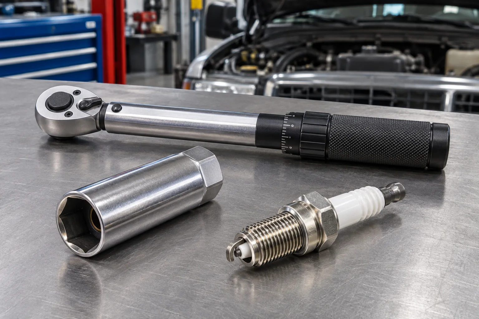
Start each plug carefully by hand with the socket and extension aligned with the well. If the plug does not thread in smoothly, check the plug, threads and alignment before applying torque. With limited access, a short extension used by hand during initial engagement can make resistance easier to notice. Follow the applicable Ford instructions for plug preparation and any compounds. Lubrication can change the clamping force produced by the same wrench setting.


The 33 lb-ft figure in Ford’s bulletin


Ford TSB 08-7-6 describes a spark plug removal concern for certain 3-valve engines. For the 6.8L, the stated applications include affected 2005–2008 F-Super Duty and 2006–2008 F-53 motorhome chassis with engines built before October 9, 2007. The bulletin gives an expected removal torque of about 33 lb-ft (45 N·m).
That value describes what a technician may encounter while removing an affected plug under the bulletin’s procedure. Choose the installation setting from the service specification for the plug being installed. If you are removing plugs on an affected build, read the bulletin and confirm its applicability before starting. Ford gives a separate procedure for the case where part of a plug remains in the cylinder head.
The bulletin addresses the early 3-valve removal concern. A 2-valve engine with damaged threads is a different repair situation. Confirm the condition of the threads before replacing the plug, particularly if the head has a prior repair. The Ford V10 service and model-year guide discusses the practical differences owners encounter.

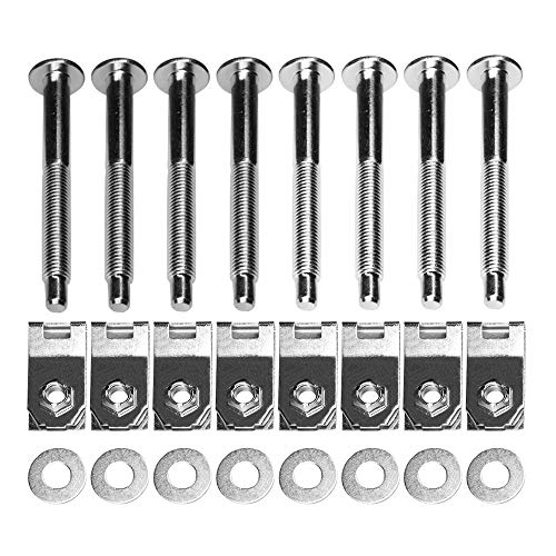

Ford 6.8 V10 cylinder head bolt torque stages


The 2004 VIN S and 2007 VIN Y procedures cited above give three passes for the head bolts. The first uses 30 lb-ft (40 N·m), followed by two separate 90° angle passes. Use new bolts as directed by Ford. The 2007 procedure explicitly identifies the original-style bolts as tighten-to-yield hardware.
- Identify the head and match it to the workshop drawing.
- Complete the 30 lb-ft pass in the numbered order.
- Restart the numbered order for one 90° pass.
- Restart the numbered order for the second 90° pass.
The rotation totals 180° for each bolt across the two angle stages. Apply the rotation in two complete passes through the group. That keeps the loading sequence consistent with Ford’s procedure. Write down which head and which pass are complete if the job stops between stages.
Do the inspection and preparation the repair manual specifies before the first pass. The head bolts are only one part of the job. You also need the correct gasket and sealing surfaces, the applicable fastener preparation, the right timing and assembly steps, and a tool that can measure rotation in the space available.
If a previous repair installed aftermarket fasteners, identify the exact hardware and obtain the instructions for it. A torque-plus-angle stage list for the Ford bolts gives the clamping procedure for those bolts. An aftermarket part may use a different lubricant and tightening method. Keep those instructions with the build record.
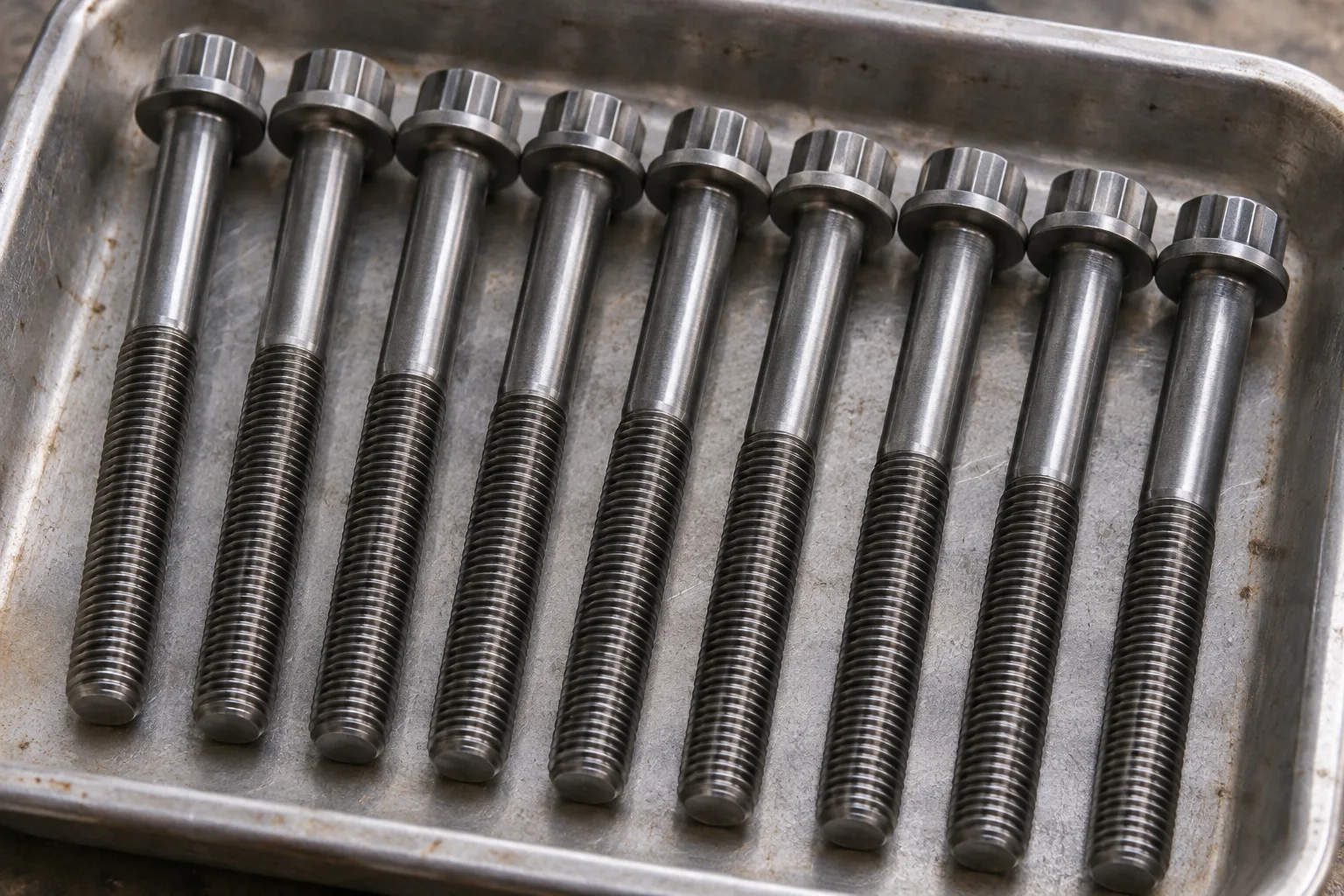
Intake manifold bolts use two unit ranges
Ford’s 2004 VIN S lower intake and 2007 VIN Y intake examples both list 2 N·m (18 lb-in) followed by 10 N·m (89 lb-in). Use the intake sequence shown in the corresponding manual. The low first pass helps identify a meaningful difference between this joint and fasteners elsewhere on the engine that share a similar-looking bolt head.
The 2004 workshop procedure separately lists an upper intake manifold stage of 2 N·m (18 lb-in) followed by 25 N·m (18 lb-ft). The two settings in that row have the same numeric value in U.S. units and differ by a factor of twelve. Record the units beside both stages and use a wrench suited to the smaller setting as well as the larger one.
Before starting the intake, identify the assembly or flange that your bolts attach. Check that the gaskets and manifold are in the position shown in the applicable manual. If a bolt reaches resistance early, check the seating surfaces and threads before pulling to the next stage.
Exhaust manifold nuts, studs and pipe joints
The documented 2004 left-hand and 2007 left- and right-hand procedures list 18 lb-ft (25 N·m) for the manifold nuts. The 2004 VIN S right-hand procedure specifies 17–20 lb-ft (23–27 N·m). Use the installation directions for the side being serviced. The 2007 VIN Y procedure also lists 9 lb-ft (12 N·m) for the studs and 30 lb-ft (40 N·m) for the manifold-to-Y-pipe or catalytic converter nuts. Confirm which interface you are holding before selecting the setting.
The named manifold nut setting applies after the hardware and gasket are positioned as required by the procedure. If a stud is damaged or has broken, identify the applicable repair method first. Torquing adjacent fasteners cannot restore the missing clamp load of a failed stud.
If you are diagnosing a tick or suspected leak, identify the leak source before starting a hardware repair. The manifold-to-head gasket and the pipe joint are separate sealing points. Check which joint you are addressing, then use the workshop section and hardware for that job.
Checks before choosing a torque setting
Write the vehicle and engine identifiers at the top of your repair notes. Next to each setting, write the joint and fastener name. This makes it easier to catch a row copied from a nearby component. On a V10, even the correct engine identification can leave more than one plug option or more than one manifold attachment point.
- Confirm whether the head and plug design match the service entry.
- Separate the intake manifold fasteners from the exhaust manifold nuts and studs.
- Copy the units along with every wrench setting.
- Put the correct numbered sequence beside any multi-stage setting.
- Record each completed torque or angle pass before moving to another job.
If a bolt, plug or stud threads differently from the others, pause to inspect it before assuming the published number will resolve the resistance. A torque specification describes a prepared assembly in a defined procedure. It does not identify a crossed thread, a mismatched bolt or a fastener that is bottoming out.
Make a work card for the specific job


For a spark plug service, record the plug part number, the build information used to select it and the installation torque. Keep the removal procedure with that card if Ford’s bulletin applies. If replacement coils are already on the engine, check the build and plug fitment with the service information before using boot color as your only clue.
For manifold work, write down the flange that each group of fasteners holds. The 2007 example has separate settings for studs, manifold nuts and pipe-joint nuts. Listing the joint with the setting helps when the same socket can reach more than one fastener in the area. Confirm the order and hardware before switching tools.
For a head replacement, record the bank and the completed pass on separate lines. Have the service drawing next to the record so another technician can see the position and stage together. If a pull is interrupted partway through an angle stage and you cannot verify how much rotation occurred, consult the applicable service procedure or a qualified technician before continuing.
Ford V10 torque specs FAQ
Why are 9 and 25 lb-ft both listed for V10 spark plugs?
Ford’s cited 3-valve reference table distinguishes early- and late-build configurations. Use the row for your actual plug and engine build. The model year can narrow the choices, while the service information and parts identification determine the applicable setting.
What is the final torque for the V10 head bolts?


The two documented factory examples use 30 lb-ft followed by two 90° passes. Ford finishes those steps with angle measurement. Use the specified sequence and the instructions for new bolts rather than searching for a final wrench torque.
Are the intake and exhaust manifold figures in the same units?
The lower or single intake stage of 89 is in lb-in. The exhaust manifold nut value of 18 in the documented procedures is in lb-ft. The 2004 upper intake uses both ranges across its two stages.
Can I use the spark plug torque from the removal bulletin?
Use the bulletin for affected removal work and the applicable plug specification for installation. The bulletin’s approximately 33 lb-ft figure refers to expected removal torque. The Ford workshop installation values listed in the chart are scoped to the documented plug configurations.
Before you tighten a Ford 6.8 V10 fastener
Confirm the engine, plug build and the exact joint in the workshop procedure. Keep the separate 2-valve and 3-valve plug values visible, use the numbered head sequence for the two angle stages, and double-check lb-in versus lb-ft before switching from intake to exhaust hardware.