
Ford 6.4 Power Stroke Torque Specs 2026 | Essential Guide

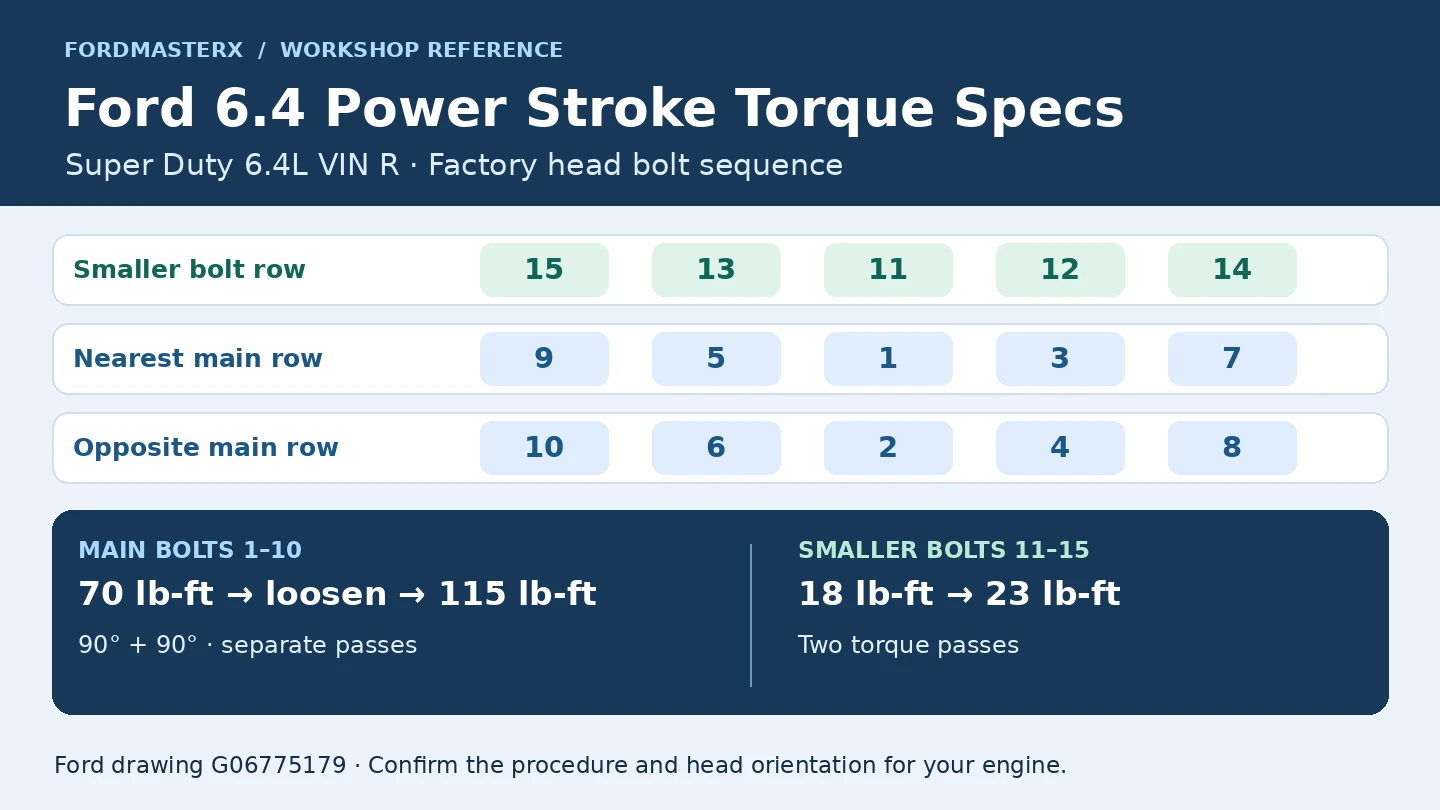
The documented Ford 6.4L Power Stroke cylinder-head procedure starts with 70 lb-ft (95 N·m) on the ten main bolts. It then calls for a loosen stage, followed by 115 lb-ft (156 N·m) and two separate 90° passes. The five smaller head bolts follow at 18 lb-ft (24 N·m) and 23 lb-ft (31 N·m). The chart below follows a Ford 6.4L VIN R workshop procedure and identifies the bolt groups in Ford’s numbered drawing.
Confirm the service section that applies to your exact truck and repair before using these values. The 2008–2010 6.4L Super Duty engine uses a different head-bolt procedure from the 6.0L Power Stroke. Aftermarket head studs have their own instructions and lubricant requirements.


Ford 6.4 Power Stroke head bolt torque sequence
This seven-stage chart follows the factory-bolt engine assembly procedure in the 2010 Super Duty 6.4L Ford workshop manual. The same stage values appear in Ford’s documented 2008 and 2009 6.4L applications. Prepare the assembly and start the new bolts by hand as directed by the applicable installation procedure before beginning the chart.
| Stage | Fasteners in Ford’s drawing | Setting |
|---|---|---|
| 1 | Main head bolts 1–10 | 70 lb-ft (95 N·m) |
| 2 | Main head bolts 1–10 | Loosen as directed in the applicable service procedure |
| 3 | Main head bolts 1–10 | 115 lb-ft (156 N·m) |
| 4 | Main head bolts 1–10 | Turn an additional 90° in sequence |
| 5 | Main head bolts 1–10 | Turn an additional 90° in sequence |
| 6 | Smaller head bolts 11–15 | 18 lb-ft (24 N·m) |
| 7 | Smaller head bolts 11–15 | 23 lb-ft (31 N·m) |
The two angle stages apply to the main bolts. Finish the first 90° pass on the group in the Ford order before starting the second. When checking the procedure at the bench, keep the stage number and bolt number separate. A marked position in the illustration identifies the bolt. The stage row tells you what to do there during a given pass.
Where the main and small bolts sit
- 15
- 13
- 11
- 12
- 14
- 9
- 5
- 1
- 3
- 7
- 10
- 6
- 2
- 4
- 8
Main bolts 1–10
70 lb-ft → loosen → 115 lb-ft → 90° → 90°
Smaller bolts 11–15
18 lb-ft → 23 lb-ft
Each angle is a separate pass in the Ford sequence. Check the applicable service drawing for head orientation.
In Ford drawing G06775179, the row of five smaller head bolts reads 15, 13, 11, 12, 14 from left to right as shown. The adjacent row of main bolts reads 9, 5, 1, 3, 7. The opposite main row reads 10, 6, 2, 4, 8. These rows reproduce the drawing’s orientation for one head. Identify the matching features in the service illustration before translating the numbers to the head in front of you.
Follow the position numbers in tightening order. Reading a drawn row left to right is useful for finding a bolt on the page, while the numeric order governs the pass. For example, position 1 is in the middle of the main row next to the smaller bolts. Position 2 is in the opposite main row. Starting from an end and sweeping across the row would apply the load in a different order.
If your manual has separate left-hand and right-hand installation sections, use the drawing it provides for the head you are servicing. The illustration here is a bench reference. The full vehicle-specific procedure establishes the orientation and gives the instructions for components removed or disturbed to reach the head.
What the loosen stage means


Ford lists a loosen stage between the 70 lb-ft and 115 lb-ft settings. Include that step when transcribing the chart to a bench checklist. A summary that shows only the two wrench settings and the two angle turns can make the loosen stage easy to miss.
The linked workshop entry lists loosening as stage 2 and retightening as stage 3. Follow the detailed wording in the applicable installation procedure for your truck rather than inferring how far to loosen or substituting a shorthand chart. If you discover that a pass was skipped after an angle stage has started, consult the applicable Ford procedure or a qualified diesel technician before applying more torque.



Ford also includes a specific instruction for bolt chatter during an angle stage. Use that instruction if it applies to the selected procedure. An unusual feel during a pull can warrant checking the bolt, threads, seating surfaces and tool access. More force on the wrench does not tell you which of those conditions is present.


Other 6.4 Power Stroke torque specs for an engine rebuild


The engine assembly chapter lists the lower crankcase main-bearing mounting bolts and the connecting rod cap bolts separately from the cylinder head bolts. These fasteners use different settings and belong to different parts of the build. The first three rows below use values documented in the Ford engine assembly chapter. Ford also uses the lower-crankcase and rod-cap stages during its clearance checks. Follow the separate final installation directions when assembling the engine. The exhaust manifold row follows the cited Ford manifold installation procedure.
| Component and fastener | Setting | What to verify first |
|---|---|---|
| Lower crankcase main-bearing mounting bolts | 110, 130 and 170 lb-ft (149, 176 and 231 N·m) | The Ford mounting-bolt diagram, bolt lengths and new bolt requirements |
| Connecting rod cap bolts | 33 then 50 lb-ft (45 then 68 N·m) | Matched cap and rod, bearing checks, and the applicable assembly procedure |
| Upper oil pan bolts | 115 lb-in (13 N·m) | Upper pan attachment and gasket placement in the illustrated procedure |
| Left exhaust manifold bolts, documented 2008 F-350 procedure | 18 lb-ft (25 N·m) on each of two passes | The Ford manifold sequence and new hardware in the left-side procedure |
The 2008 F-350 left exhaust manifold installation uses the same torque value for two separate passes. The nearby turbocharger inlet pipe joints and bracket hardware have their own instructions. Follow the location illustration before applying the 18 lb-ft value to a fastener you can reach from the same side of the engine.
The 2008 Ford engine specification section gives additional component values. It refers the reader to component procedures for selected multi-stage fasteners. Use the specification page to identify the component and the procedure to check sequence, fastener condition and preparation.


Watch the units on pan and cover hardware
The upper oil pan uses 115 lb-in, while the third main head-bolt stage uses 115 lb-ft. The number looks identical on a quick checklist. The unit changes the applied torque by a factor of twelve. Write the unit on the work card beside the number and check which scale or mode the wrench displays before pulling.
Use a tool whose operating range fits the value and whose drive and socket fit the fastener. A wrench chosen for the lower crankcase bolts may be awkward or unsuitable at the oil-pan setting. Separate the tools by the job they are being used for, especially when the build moves between the lower crankcase and the engine top end on the same bench.
Main bearing and connecting rod caps need their own setup



The lower crankcase is part of the main bearing support. Ford gives a dedicated mounting-bolt sequence and identifies different bolt lengths. The position of a bolt matters before the first pass. During trial checks, record the measurements and follow the specified sequence for checking clearances. During final assembly, verify the fastener preparation and installation requirements again.
Connecting rod cap bolts have their own two-pass setting. Match each cap to its rod and confirm the bearing arrangement and clearances before the final torque passes. The 50 lb-ft final value belongs to the rod-cap procedure in this application. A convenient torque value cannot correct a misplaced cap or a bearing clearance outside the workshop limits.
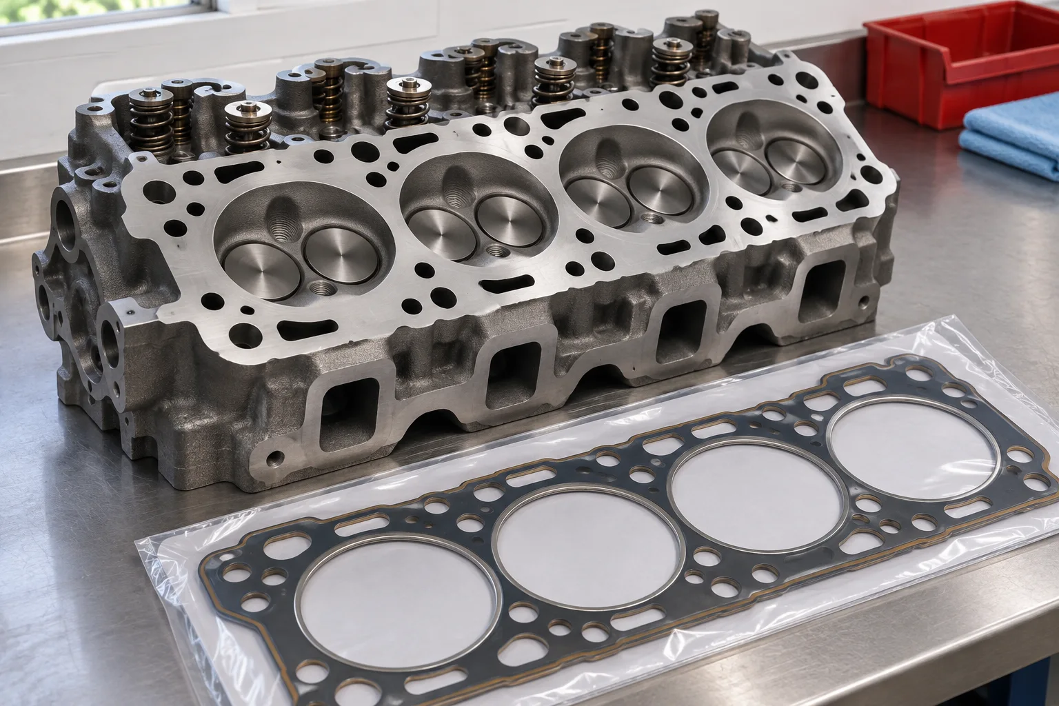
Prepare the head and new bolts before torquing


Ford’s assembly instructions specify lightly lubricating the threads and flanges of the new main bolts with clean engine oil. They caution against excess oil and substitutions such as grease or anti-seize on those threads. Use the specified preparation because a change in friction can change how much bolt tension the same wrench setting produces.
Identify which fasteners are the long main cylinder-head bolts and which are the five smaller head bolts. Keep them separate from rocker, cover and bracket hardware. The engine’s top end has several fasteners of similar appearance, especially when everything has been moved to one tray. A labeled work surface and a copy of the appropriate illustration make it easier to put each part back in its own group.
Confirm that the gasket and dowels fit the head and block before tightening. Follow the inspection and cleaning directions for the sealing surfaces and bolt holes. If a bolt will not start and seat by hand as described in the manual, determine what is obstructing it. A wrench can register torque from interference before the head sees the intended clamp load.
Use a readable angle tool for the two 90° stages. Plan clearance around the cab, body or stand before beginning. If the job is interrupted, write down the head, stage and last confirmed bolt position. If the angle already applied is uncertain, verify the recovery method in the correct service information before turning the bolt further.
The 6.4 Power Stroke engine diagram can help with component identification. If you are considering the cost of a repair rather than working on the head now, the 6.4 Power Stroke used-truck guide gives broader repair context.
6.4 Power Stroke factory bolts versus ARP head studs
For factory bolts, use the Ford head-bolt sequence, lubricant and stage list applicable to the engine. For aftermarket studs, match the kit number to its installation sheet before setting the wrench. Stud material, washers, lubricant and nut torque all belong to the kit’s procedure.
As one example, ARP’s 250-4203 instructions give the main stud nut stages as 90, 180 and 275 lb-ft with ARP Ultra-Torque. The same sheet gives 25 lb-ft for the smaller M8 hardware. These are the settings for the cited kit. Verify the latest instructions for the kit in hand if its number or hardware differs.
The Ford 115 lb-ft setting belongs to a stage before two angle passes on the original-style main bolts. The ARP values belong to the stud-and-nut installation. Write the kit number and lubricant beside the torque values if the engine uses studs, so the next person working on it can identify the instruction set.
Keep the measurements with the engine build record
A useful work record identifies the engine, the two heads, the fastener type, the applicable Ford procedure and the checks performed before assembly. For a short block, keep the rod or bearing clearance measurements with the corresponding positions. For a head job, record the gasket and bolts used and which tightening pass was completed. The next technician can then distinguish a checked assembly from one that has only been set in place.
If you are troubleshooting coolant loss or another symptom before deciding to disassemble, record the conditions in which the problem appears. Confirm the diagnosis and the relevant inspection steps first. A torque table is most useful after you know which parts need service. It cannot establish that the head gasket has failed or that tightening the installed bolts will resolve the original symptom.
Ford 6.4 Power Stroke torque FAQ
Is 115 lb-ft the final head bolt setting?


It is the torque setting before the two angle passes in the documented factory-bolt procedure. The main group then receives two distinct 90° passes in the Ford sequence. The small group ends at 23 lb-ft in that procedure.
Do the five smaller head bolts get an angle pass?
The Ford chart calls for 18 lb-ft and 23 lb-ft on positions 11–15. The angle stages apply to positions 1–10. Check the fastener group in the Ford drawing if you are working from a partially disassembled engine or unfamiliar hardware.
Can the 6.0 and 6.4 factory-bolt procedures be interchanged?
Each engine has a separate procedure. The 6.4 chart documented here includes the 70 lb-ft pass, a loosen stage, 115 lb-ft and two angle passes. Use the 6.4 workshop information for the exact engine you have. An internet table with a similar drawing can still belong to a different engine.
Why does the exhaust manifold repeat the same value?
The documented left manifold installation calls for two passes in the specified sequence, each at 18 lb-ft. That gives you two checks through the group at the prescribed setting. Use the full manifold procedure to identify the correct mounting fasteners, side and replacement hardware.
Before the wrench goes on the first bolt
For this Ford 6.4 Power Stroke torque chart, keep the correct service illustration open beside the stage list. Confirm the engine, fastener type, lubricant, units and the stage already completed. The head, lower crankcase, rods and manifolds each have distinct settings. Use the instructions for the assembly you are working on and document each completed stage before moving on.