
Ford 6.0 Power Stroke Head Bolt Torque 2026 | Essential Specs

Ford’s documented 2007 Super Duty 6.0L Power Stroke procedure specifies 65 lb-ft (88 N·m), then 85 lb-ft (115 N·m), then three separate 90° clockwise passes for the ten main cylinder head bolts. The five smaller head bolts follow at 18 lb-ft (24 N·m), then 23 lb-ft (31 N·m). For this procedure, use new factory-style main bolts and confirm the tightening sequence in the current service procedure for the exact vehicle and engine.
An archived Ford procedure for the 2005 Super Duty differs at the 85 lb-ft stage. It calls for that pass on bolts 1, 3, 5, 7 and 9. The 2007 Ford procedure cited here shows all ten bolts at 85 lb-ft. This makes the document revision and the bolt-position drawing important checks before you start.


Ford 6.0 Power Stroke head bolt torque chart
The table below follows the Ford workshop procedure for the 2007 Super Duty 6.0L diesel, engine VIN code P. Read each row as a complete pass on one cylinder head. Bolt numbers are sequence positions in the Ford drawing. Check the driver- and passenger-side illustrations for your application before identifying a position on the engine.
| Pass | Head bolt positions | Setting | What changes |
|---|---|---|---|
| 1 | Main bolts 1–10 | 65 lb-ft (88 N·m) | Apply initial torque in the numbered order. |
| 2 | Main bolts 1–10 | 85 lb-ft (115 N·m) | Apply the second torque pass in the numbered order. |
| 3 | Main bolts 1–10 | 90° clockwise | Make the first angle pass. |
| 4 | Main bolts 1–10 | Another 90° clockwise | Restart at position 1 for the second angle pass. |
| 5 | Main bolts 1–10 | Another 90° clockwise | Restart at position 1 for the third angle pass. |
| 6 | Smaller bolts 11–15 | 18 lb-ft (24 N·m) | Apply the initial torque to the smaller group. |
| 7 | Smaller bolts 11–15 | 23 lb-ft (31 N·m) | Apply the final torque to the smaller group. |
See the seven stages and the matching drawing in the linked Cab & Chassis service entry for the 2007 Super Duty Ford workshop stages and drawing. The three angle stages follow the two torque stages. The smaller group uses torque settings throughout.
The numbers are the pairs printed in the service procedure. If you use a metric wrench, select the listed N·m value. For example, stage 6 is 24 N·m, which Ford prints alongside 18 lb-ft. The final small-bolt pass is 31 N·m or 23 lb-ft. Reading the metric column as lb-ft would change the load on the fasteners.
How to read the cylinder head bolt sequence


- 15
- 13
- 11
- 12
- 14
- 10
- 6
- 1
- 3
- 7
- 8
- 4
- 2
- 5
- 9
Main bolts 1–10
65 lb-ft, 85 lb-ft, then three separate 90° clockwise passes.
Smaller bolts 11–15
18 lb-ft, then 23 lb-ft.
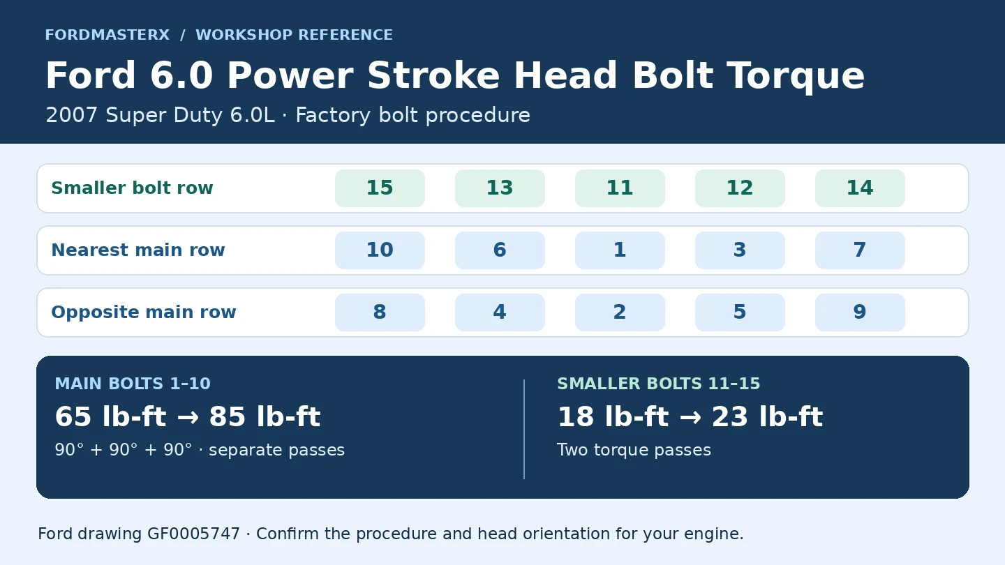
Numbers mark tightening order. Match the head and orientation to the applicable Ford drawing before using these positions. The archived 2005 workshop print uses a different map and 85 lb-ft pass.
Use the location drawing in the same service document as your torque table. Identify the head and the orientation in that drawing before marking positions. A sketch copied out of context can look usable when it is rotated, mirrored, or based on another service revision. A number on the drawing tells you the tightening order, while the stage table tells you the setting for that pass.
In the illustrated 2007 Ford view, the smaller row reads 15, 13, 11, 12, 14. The main row nearest it reads 10, 6, 1, 3, 7, and the opposite main row reads 8, 4, 2, 5, 9. These are the positions as printed in the drawing. Confirm how your cylinder head is oriented in the matching service illustration.
In the 2007 procedure above, the ten M14 main bolts are positions 1 through 10 and the five M8 head bolts are positions 11 through 15. Begin each main-bolt pass at position 1, work through position 10, and return to position 1 for the next pass. Complete all three angle passes on the main group before moving to the smaller group.
When you are sorting parts on the bench, keep the fifteen head fasteners separate from bolts for the rocker arm carrier, valve cover, or other assemblies. An M8 thread size can appear on more than one component. Use the workshop procedure that names the part you are installing. If you are actually looking for the upper cover hardware, see the 6.0 Power Stroke valve cover bolt layout.


Why three 90° passes matter
The three angle passes add up to 270° of rotation per main bolt after the torque stages. That total describes what each bolt receives across the procedure. Ford’s sequence applies 90° to every main bolt before applying the next 90° to the group. Turning one bolt the full 270° before moving on would change how the head is loaded as the fasteners are tightened.


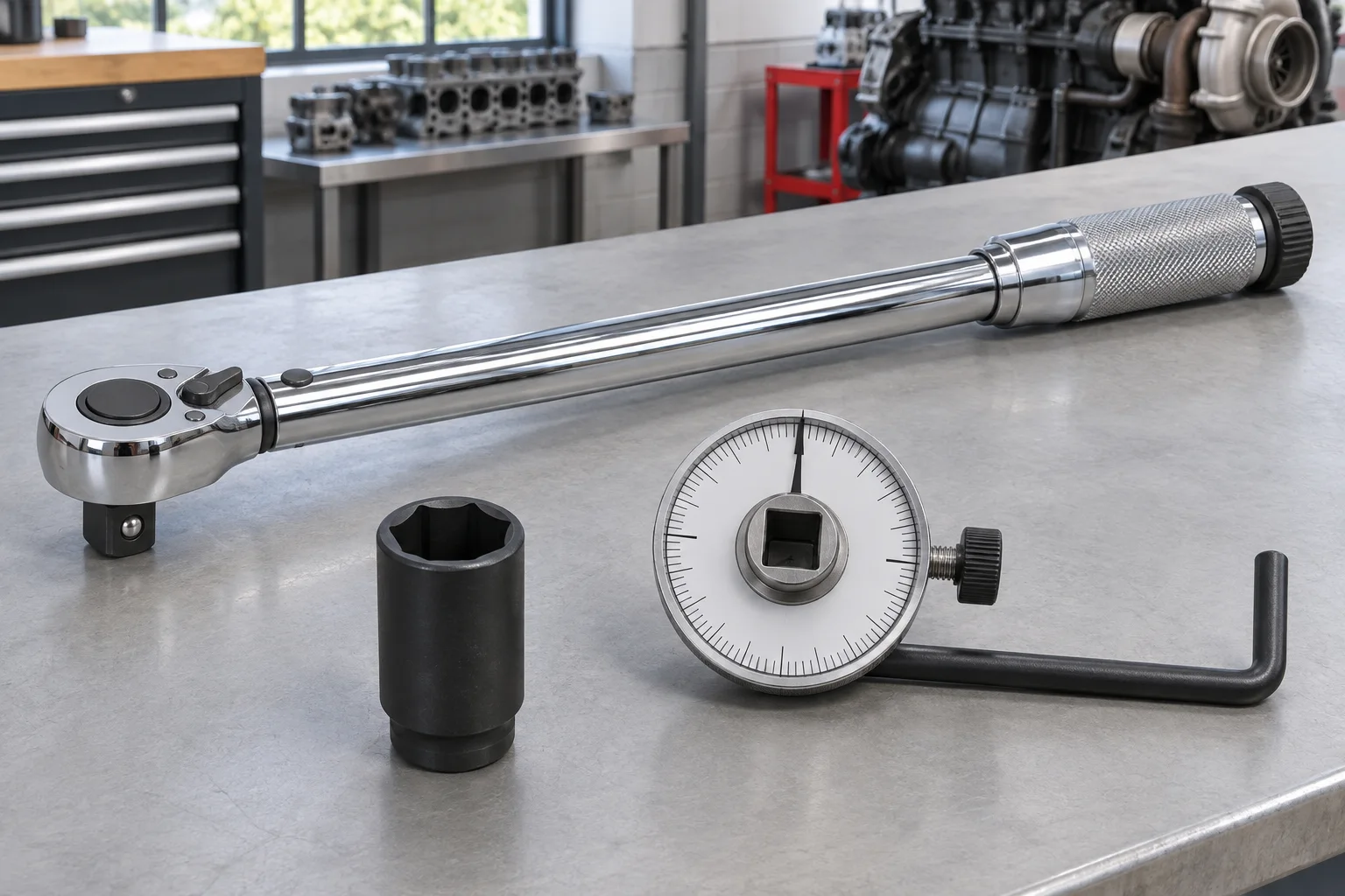
Use a torque wrench for the first two passes and an angle gauge or a torque wrench with a suitable angle mode for the next three. Select equipment that fits the available space and lets you see when the commanded rotation is complete. If a bolt is difficult to reach, plan the access before beginning the angle pass. Changing your hand position during the pull is easier to manage when you can keep track of rotation at the fastener.
A printed checklist with one line per stage gives you a record if you are interrupted. Mark a pass complete when every bolt in that group has reached the specified setting. If you lose track of a bolt’s angle, pause and refer to the service procedure or a qualified diesel technician before adding more rotation. The torque reading after an angle pass is affected by the assembly and offers no reliable substitute for knowing the rotation already applied.
Why some Ford documents list five bolts at 85 lb-ft

The archived 2005 Super Duty workshop procedure, section 303-01C-11, specifies 65 lb-ft for bolts 1–10 and 85 lb-ft for positions 1, 3, 5, 7 and 9. It then gives three 90° passes on positions 1–10 and the same 18 and 23 lb-ft passes on positions 11–15. The archived drawing and stages belong together.


The documented 2007 Super Duty workshop specification instead lists 85 lb-ft for positions 1–10. The two workshop references use different bolt-position drawings as well. The archived document identifies an application and print revision. Confirm the applicable repair procedure from the vehicle and engine information before choosing a map or a set of stages.
Look up the current Ford workshop information for your VIN, select the 6.0L diesel engine and find the cylinder-head installation section. Check for a related Ford service bulletin and confirm which procedure covers the repair you are performing. If the truck has a replacement long block or remanufactured heads, record that detail and verify which hardware is installed before ordering parts or choosing the sequence.
What the year and VIN do tell you


The VIN and vehicle model narrow the workshop information you need. A 6.0L Super Duty, Excursion, or E-Series can share basic engine architecture while having different service access and application-specific instructions. The complete repair procedure also identifies operations for the fuel lines, pushrods, rocker assemblies, and other components disturbed during a head job.
If you are looking at a bare engine on a stand, verify its identification and the parts on it. Vehicle registration alone can identify the truck that received the engine, even if that engine or the heads came from another application. The installation document should fit the engine and hardware in front of you.
New bolts, clean oil and head-gasket fitment
The Ford workshop instructions call for lightly lubricating the threads and flanges of the new main cylinder head bolts with clean engine oil. They caution that excess oil and other lubricants can affect the assembly. Check that the bolt holes and sealing surfaces are prepared as specified in the full workshop procedure before placing the gasket and head.
Start the retaining bolts by hand as the manual directs. If a bolt binds early or a flange will not sit against the intended surface, check the bolt, thread condition, hole and alignment before applying wrench force. A torque reading from a fastener that is binding or bottoming can give a misleading impression of clamp load. Reusing removed factory main bolts also conflicts with the replacement procedure documented by Ford.
Set aside enough time to inspect the heads and block deck before assembly. A reliable tightening sequence helps apply the designed clamp load to an assembly that already fits correctly. It cannot compensate for a sealing surface outside the workshop limits, a damaged thread, or an incorrect gasket. If coolant loss led to the repair, identify the failure path before assuming the head gasket was the source. The reason for coolant loss matters because the EGR cooler and other cooling-system components can require their own diagnostic checks.
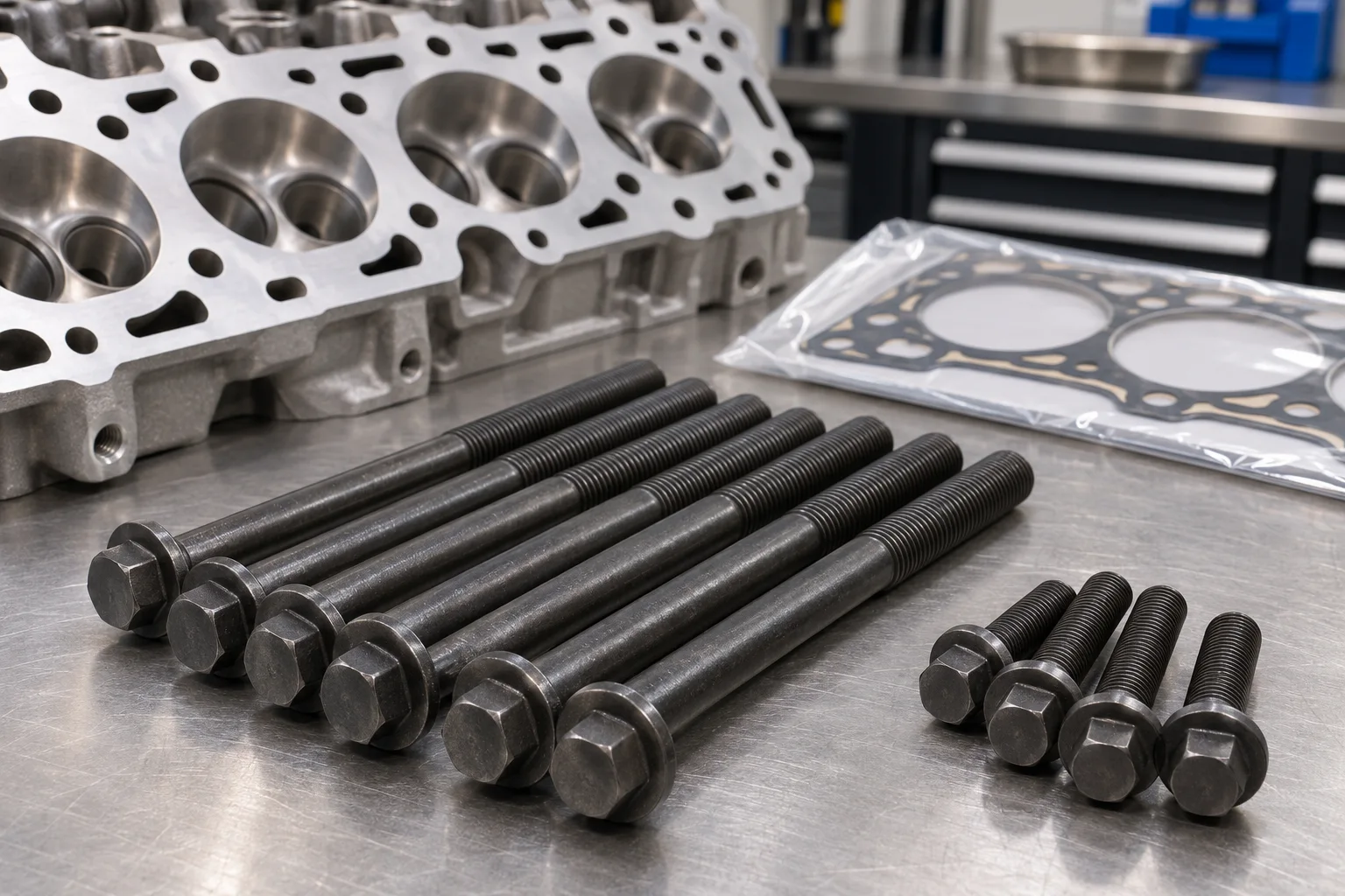
Check head locating dowels and gasket fit
Ford TSB 07-10-4 identifies straight 18 mm head dowels on pre-commonized assemblies and straight 20 mm dowels on commonized assemblies. Some previously repaired pre-commonized engines can have 18-to-20 mm step dowels. Ford explains that prior service can change which head configuration you find on an earlier engine.
Use the bulletin and the physical parts to verify the head, dowel and gasket combination. A dowel measurement answers a fitment question. Select the bolt sequence from the applicable cylinder-head installation document, and identify the rocker-carrier hardware separately. An old invoice or the truck’s model year can help you find the right catalog entry, but checking the actual assembly resolves uncertainty after an engine or head replacement.
If you need orientation while identifying parts around the top of the engine, use the 6.0 Power Stroke engine bay diagram. The cylinder-head diagram in the workshop manual remains the reference for numbered fastener positions.
Factory bolts versus aftermarket head studs
The Ford torque-plus-angle steps apply to the factory-style bolt procedure described above. An aftermarket stud has its own instructions covering lubricant, washers, nut torque and tightening order. Identify the exact kit from its packaging or documentation before using its settings.
For example, ARP kit 250-4202 instructions specify 210 lb-ft for the main stud nuts in three equal steps with ARP Ultra-Torque, and 23 lb-ft for the OEM smaller head bolts in that installation. The instructions for the separate Custom Age 625 Plus kit 250-4205 give different settings. Use the sheet for your exact kit and follow its instructions for the smaller hardware as well.
The ARP instructions also identify where the assembly lubricant goes. That matters because the relationship between wrench torque and fastener tension changes with lubrication. Mixing a Ford bolt specification, a stud-kit value and a lubricant chosen from a different instruction set makes the resulting load hard to predict. Keep the kit sheet beside the wrench so the target and the lubricant stay tied to the hardware in use.
A check before the first torque pass
- Match the service procedure and drawing to the vehicle, engine and repair.
- Confirm the head and gasket fit, the dowels are correct, and the sealing surfaces meet the applicable workshop checks.
- Separate the new factory-style main bolts from the smaller cylinder-head bolts and unrelated fasteners.
- Set out the correct torque and angle tools and confirm there is room to use them on the chosen head.
- Check which positions receive the 85 lb-ft pass and have the exact numbered diagram visible.
- Track each completed pass for that head. Refer to the service procedure for any interrupted or uncertain tightening step.
These checks help catch setup errors before the bolts reach the angle stages. They also make it easier to hand off a paused job to another technician. Record which manual or kit sheet you used and which head and stage were completed.
Ford 6.0 head bolt torque FAQs
Do all 6.0 Power Stroke head bolts get 85 lb-ft?


The documented 2007 Super Duty procedure calls for 85 lb-ft on main positions 1–10. The archived 2005 Ford print calls for that value on positions 1, 3, 5, 7 and 9. The smaller positions 11–15 have their own lower settings. Check the current procedure for the exact vehicle and keep its drawing with the stages.
What is the final torque for the five smaller head bolts?
For the 2007 and archived 2005 Super Duty workshop procedures cited here, the final value is 23 lb-ft (31 N·m) after an 18 lb-ft (24 N·m) pass. This applies to the five smaller cylinder-head bolts in those procedures. An aftermarket kit that supplies its own smaller hardware can specify a different setting.
Can I reuse the original main head bolts?

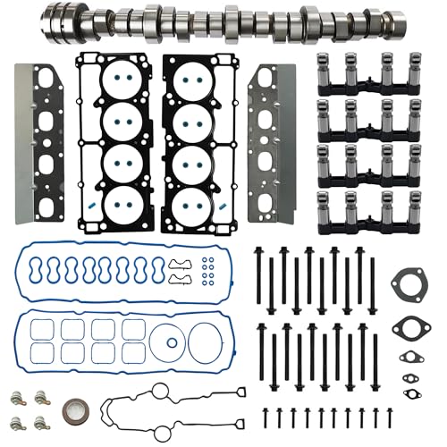
Use new main bolts when following the factory-style Ford procedure documented here. The workshop instructions specify new cylinder head bolts for installation. If you are working with a reusable aftermarket stud system, check the kit manufacturer’s inspection and reuse instructions for that particular hardware.
Is 270° a final torque specification?
It is the sum of three 90° rotations in the cited factory procedures. Apply each 90° as its own complete pass in the specified order after the initial torque stages. Set the torque wrench in lb-ft or N·m for the initial torque passes and use angle measurement for the rotation passes.
Does an 18 mm or 20 mm dowel determine the bolt order?
Use the dowel size to verify head and gasket compatibility. Use the applicable Ford procedure and its matching diagram for the bolt order. Some service-repaired engines have stepped dowels or replacement heads, so it is worth checking the hardware as well as the vehicle record.
Before you close up the engine
For the documented 2007 Super Duty factory procedure, the Ford 6.0 Power Stroke head bolt torque schedule is 65 and 85 lb-ft on the ten main bolts, three 90° passes, then 18 and 23 lb-ft on the five smaller bolts. Verify which bolts receive the 85 lb-ft pass before tightening. Use the diagram that belongs to the selected procedure, and follow the exact kit sheet if you are fitting aftermarket studs.