2026 Ford F150 Air Intake Diagram: Troubleshooting & Repair Guide

The 2026 Ford F150 air intake assembly routes from the front grille inlet through the mass airflow sensor (MAF) housing to the turbocharger or throttle body. Ensure all vacuum lines are seated. Standard intake clamp torque spec is 35-40 inch-pounds to prevent leaks that trigger an OBD-II lean diagnostic code.
📌 Key Takeaways
- Maintain clamp torque specifications of 35-40 inch-pounds to prevent vacuum leaks.
- The MAF sensor is the primary feedback loop to the ECU for fuel trim adjustments.
- An improperly seated air filter housing will trigger a P0171 or P0174 diagnostic code.
- Check all silicone couplers for cracks, as they are the most common source of unmetered air entry.
- Professional diagnostics are required if the ECU reports persistent air-to-fuel ratio faults despite intact hardware.
Maintaining the induction integrity of a Ford F-150 is critical for preserving engine efficiency, power delivery, and fuel economy. Whether you are troubleshooting a lean running condition or performing routine maintenance, understanding the ford f150 air intake diagram is the foundational requirement for accurate diagnostics. The modern induction system is a highly calibrated environment where the PCM relies on precise data from sensors to calculate air-fuel ratios. Improperly seated clamps, vacuum leaks, or contaminated sensors can trigger a diagnostic code, forcing the vehicle into a restricted performance mode. This guide provides a deep technical analysis of the F-150 intake architecture, from the snorkel inlet to the throttle body, to help you resolve complex performance issues effectively.
Decoding the Ford F150 Air Intake Diagram and Essential Components

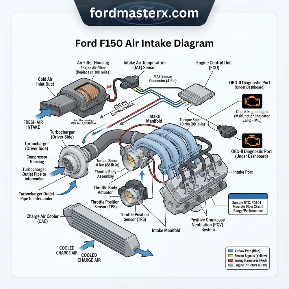
The Ford F-150 induction system is engineered for laminar flow and acoustic dampening. Referencing the ford f150 air intake diagram, the process begins at the hood-level air inlet. Outside air is drawn through the snorkel and into the air cleaner housing. This housing contains the filter media, designed to trap particulates while minimizing pressure drop. In 5.0L Coyote and 3.5L EcoBoost configurations, the airbox design varies slightly to accommodate turbo piping or larger displacement volume requirements, but the fundamental logic remains identical.

Following the airbox, the system enters the intake tube, which features the Mass Air Flow (MAF) sensor (or Manifold Absolute Pressure sensor on certain forced-induction models). The MAF sensor is the primary reporting device for the ECU, measuring the mass of air entering the engine. As airflow passes over the heated wire or film of the MAF sensor, the cooling effect allows the ECU to calculate the exact fuel pulse required. Any turbulence in this region, often caused by loose clamps or cracks in the plastic bellows, results in skewed data, triggering an OBD-II check engine light.
Beyond the MAF, the intake tract includes the resonator box. This chamber is specifically designed to eliminate intake harmonic noise. While some enthusiasts remove these for sound, they play a role in maintaining consistent airflow velocity at lower RPMs. The assembly terminates at the throttle body. The throttle body houses the Throttle Position Sensor (TPS) and the actuator motor, which works in conjunction with the ECU to regulate engine load. Tightening hardware in this area requires strict adherence to torque specs, as plastic housings are prone to warping or cracking if overtightened during installation.
Airbox lid fasteners: 4 Nm (35 lb-in). Intake tube hose clamps: 3 Nm (26 lb-in). Throttle body mounting bolts: 10 Nm (89 lb-in). Always verify these values against your specific model year service manual, as aluminum manifold assemblies may differ from plastic composite intakes.
Common Ford F150 Air Intake Diagram Problems and Symptoms


Component failure within the intake tract usually manifests as driveability issues rather than total system collapse. By observing the ford f150 air intake diagram during inspection, you can isolate which segment of the induction path is failing. For instance, a cracked air intake boot causes unmetered air to enter the system, leading to a lean condition (P0171/P0174 codes).
| Symptom | Potential Intake Fault | ECU Impact |
|---|---|---|
| Rough Idle/Surging | Vacuum leak post-MAF | Fuel trim correction limits exceeded |
| Reduced Power/Limp Mode | Dirty MAF Sensor | Invalid air mass readings |
| Check Engine Light | Disconnected IAT Sensor | Default air temp mapping engaged |
| Poor Acceleration | Collapsed intake resonator | Increased intake restriction |
The Air Filter Minder, commonly found on older F-150 models, serves as a visual indicator of system restriction. If this turns yellow or red, the pressure drop across the filter media has exceeded factory thresholds, negatively impacting oil pressure requirements by forcing the engine to work harder during high-load scenarios. While not directly related to mechanical oil pressure, excessive vacuum load can lead to increased stress on internal components, potentially shortening the service life of timing chain tensioners due to inconsistent engine load cycling.
Diagnosing Ford F150 Air Intake Performance Problems
When you encounter a diagnostic code linked to the air intake system, follow a systematic approach to avoid “parts-swapping” fatigue. The goal is to verify the integrity of the air path between the intake snorkel and the engine manifold.
- Scan and Record Diagnostic Codes: Connect an OBD-II scanner to extract all stored codes. Look specifically for P0100–P0104 (MAF circuit) or P0171/P0174 (System Lean).
- Visual Inspection of the Intake Tract: Inspect all rubber bellows and couplers for dry rot or tears. Use a spray bottle with water or a dedicated smoke machine to check for vacuum leaks. Ensure all clamps are torqued to factory specifications.
- Analyze MAF/IAT Sensor Data: Using a professional scan tool, monitor live data for the Mass Air Flow sensor. At idle, a healthy 5.0L engine should show a consistent Grams Per Second (GPS) reading. Fluctuations or flatline readings indicate a faulty sensor or frayed wiring harness.
- Throttle Body Inspection: Remove the intake tube at the throttle body. Inspect the butterfly valve for carbon buildup. If the plate does not move freely or is blocked by sludge, perform a cleaning with an approved throttle body cleaner, taking care not to force the plate open, which can damage the internal motor gears.
- PCM/ECU Learning Reset: After cleaning or replacing components, perform a PCM reset to clear learned fuel trims. This ensures the ECU does not continue to compensate for a fault that has already been corrected.
Never use aggressive solvents or metallic brushes on MAF sensor elements. The sensor utilizes a delicate thermistor that is easily destroyed by physical contact or harsh chemicals. Use only electronics-safe MAF cleaner sprays.
Upgrading to a Cold Air Intake vs Stock Systems
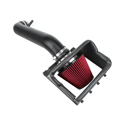
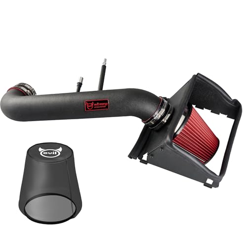
Performance enthusiasts often debate the efficacy of aftermarket cold air intakes (CAI) versus stock OEM systems. The primary difference lies in the intake tube diameter and the surface area of the filtration element. According to the ford f150 air intake diagram, the stock system is designed for silence and low-speed throttle response. Aftermarket intakes generally remove the resonator chambers to increase airflow velocity and induction sound.
| Feature | Stock OEM System | Aftermarket CAI |
|---|---|---|
| Airflow Design | Resonated/Quiet | High-flow/Direct path |
| ECU Compatibility | Factory optimized | May require custom tuning |
| Maintenance | Paper element/Frequent | Reusable/Oiled |
If you install a CAI, it is imperative to verify whether the design changes the air velocity profile over the MAF sensor. If the intake diameter is larger than stock, the ECU may incorrectly calculate the air-fuel ratio, resulting in lean running conditions. In such cases, an ECU tune is mandatory to recalibrate the mass air flow tables. Failing to adjust for increased air density can lead to engine pinging or long-term damage, particularly when the system is under high load and the timing chain is subjected to maximum torque values.


Is it necessary to reset the ECU after cleaning the intake components?
Yes, clearing the KAM (Keep Alive Memory) in the ECU allows the engine to relearn idle strategies based on the new, clean airflow data. Without this reset, the PCM may continue to apply fuel trim offsets designed for a dirty or restricted intake, leading to sub-optimal performance.


Can coolant flow issues affect intake performance?


While the intake system and cooling system are separate, the throttle body in many F-150 models is heated by engine coolant. If this circuit is clogged or leaking, it can lead to erratic throttle response in cold climates as the butterfly valve may stick or icing may occur. Always check coolant levels if you experience persistent throttle sticking.
How often should the MAF sensor be cleaned?
Under normal operating conditions, the MAF sensor does not require a specific service interval. However, if you are using an oiled aftermarket air filter, you should inspect and clean the MAF sensor every 15,000 miles, as oil mist can migrate and coat the sensor element, skewing your diagnostic readings.
Does a faulty air intake cause low oil pressure warnings?


A faulty air intake system does not directly influence oil pressure sensors. However, severe induction leaks can cause the engine to run lean and hot, which may lower oil viscosity and indirectly affect oil pressure readings. If you have both intake faults and low oil pressure, prioritize the oil system to prevent catastrophic engine failure.


For those managing F-150 fleets or specialized equipment, document all intake modifications in your service logs. Variations in intake vacuum can mask other symptoms like timing chain stretch or valve train noise, making it difficult to differentiate between induction issues and internal mechanical wear.
Step-by-Step Guide to Understanding the Ford F150 Air Intake Diagram
Identify – Locate the air intake path from the grille inlet to the engine throttle body.
Locate – Find the MAF sensor connector and verify the wiring harness is free of tension.
Reference – Match the diagram components against the physical layout of your engine bay.
Connect/Route – Secure all vacuum lines and tighten intake clamps to 35-40 inch-pounds.
Verify – Clear the ECU diagnostic codes using an OBD-II scanner and perform a test drive.
Troubleshoot – Inspect for air leaks or sensor faults if the check engine light returns.
Ford f150 Air Intake Diagram: Frequently Asked Questions
What does the ford f150 air intake diagram show?
The diagram displays the full flow path from the fresh air inlet ducting to the resonator, air filter box, MAF sensor housing, and throttle body inlet tube. It highlights critical sensor locations, vacuum port connections, and the specific orientation of the intake air temperature (IAT) sensor within the assembly.
How do I read the ford f150 air intake diagram?
Start by identifying the filter housing as the central point. Follow the arrows representing airflow direction toward the engine block. Identify components by matching the schematic shapes to your engine bay. Look for specific callouts indicating electrical connector paths to the ECU and vacuum line attachment points.
What are the main components in ford f150 air intake diagram?
Key components include the cold air induction tube, air cleaner element housing, mass airflow (MAF) sensor assembly, resonator box, and the turbo inlet adapter. Also depicted are the secondary air injection lines and the breather hoses that connect from the valve cover to the main intake pipe.
What are common problems with ford f150 air intake diagram?
Common issues include loose intake clamps causing vacuum leaks, cracked rubber bellows leading to unmetered air, and dirty MAF sensor wires causing erratic engine performance. These failures frequently trigger a check engine light and stored OBD-II codes related to bank 1 or bank 2 lean fuel conditions.
Can I use ford f150 air intake diagram for DIY repair?
Yes, the diagram is essential for ensuring correct component alignment and verifying that all sensor harnesses are properly routed. It helps prevent accidental damage during filter replacement or aftermarket cold-air intake installations, ensuring you maintain a sealed system that prevents engine performance degradation.
What tools do I need for ford f150 air intake diagram?
You will need a set of metric sockets (7mm and 8mm for clamps), a flathead screwdriver for stubborn connectors, and a torque wrench calibrated for inch-pounds. A digital multimeter is also useful for testing the MAF sensor signal voltage when troubleshooting persistent diagnostic codes.