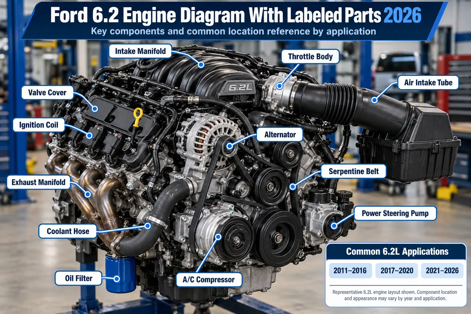
Ford 6.2 Engine Diagram With Labeled Parts and Locations 2026

A Ford 6.2 engine diagram helps you identify service points, cylinder banks, and internal engine parts on the 6.2L Boss gasoline V8. The correct reference depends on whether you own an F-150 or first-generation Raptor, an F-250, or an F-350, because the engine compartment layout is not identical across these trucks.
For a quick under-hood check, start with Ford’s model-year-specific overview. Use a cylinder-bank diagram for a misfire or ignition question, and an exploded assembly drawing when you need to identify a part inside the engine. This guide explains what each type shows, how to orient it, and where to find the details without mixing up engine families.
Gasoline V8 Engine Reference
Ford 6.2L Boss V8 Cylinder Map
Cylinder numbering, bank orientation and firing order
How to read the diagram
Orientation: Left and right refer to the seated driver’s viewpoint. Standing at the grille reverses what appears on your left and right.
Use: A cylinder-location reference, not a repair or belt-routing diagram.
Verified Firing Order
Read left to right. Firing sequence is different from cylinder numbering.
Schematic only; not to scale. Based on the Ford 6.2L gasoline V8 cylinder layout and Ford 2017 Super Duty firing-order specification. Check the owner or service manual for your model year before repairs.
Ford 6.2 Engine Diagram With Labeled Components
Recommended Best Deal Products


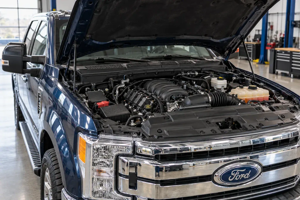
The clearest starting point for an F-250 or F-350 owner is the 6.2L under-hood overview in the truck’s owner’s manual. It labels the service points you can reach with the hood open, rather than showing every internal engine component.
For example, the 2017 Ford Super Duty 6.2L under-hood diagram uses callouts A through J. Those callouts identify the air filter, engine-compartment fuse box, automatic-transmission-fluid dipstick, brake-fluid reservoir, washer-fluid reservoir, coolant reservoir, power-steering-fluid reservoir, engine-oil filler cap, engine-oil dipstick, and battery.
The illustration is an engine-bay reference, not a bare-engine cutaway. Some labelled items, such as the battery and brake-fluid reservoir, sit around the engine rather than on its block. That distinction matters if you are searching for a water pump, timing chain, crankshaft sensor, or an engine mounting point. An under-hood overview may not show those items at all.
The 6.2L Boss is a longitudinal V8, meaning the crankshaft runs front to rear in the truck. In the diagrams below, front means the radiator and accessory-drive end; rear means the transmission and firewall end. Driver and passenger sides always refer to the sides of the truck as seen from the seated driver’s position, not your left and right while standing at the grille.
When comparing your truck with a diagram, first match the model year and engine. The next table translates Ford’s 2017 callouts into useful identification clues.
Where Are the Main 6.2 Engine Parts Located
Ford’s 2017 Super Duty 6.2L diagram provides ten identification points. Use its letters with the factory illustration, rather than treating this table as a universal physical map for every 6.2L truck.
| Ford Label | Component | What to Look For |
|---|---|---|
| A | Air filter | Air-cleaner housing and intake ducting |
| B | Engine-compartment fuse box | Covered electrical distribution box |
| C | Automatic-transmission-fluid dipstick | Transmission-fluid level-check handle or tube shown on this model |
| D | Brake-fluid reservoir | Small brake-fluid container near the master cylinder |
| E | Windshield-washer-fluid reservoir | Filler neck marked for washer fluid |
| F | Engine-coolant reservoir | Coolant expansion or degas bottle |
| G | Power-steering-fluid reservoir | Hydraulic steering-fluid container |
| H | Engine-oil filler cap | Oil-fill opening on the engine |
| I | Engine-oil dipstick | Engine-oil level-check handle |
| J | Battery | Main 12-volt battery shown in the reference |
The oil filler cap and oil dipstick serve different jobs. The filler cap is where the specified engine oil goes; the dipstick is for checking the oil level. Neither tells you the correct oil grade, capacity, or filter without consulting the specifications for your exact truck.
Likewise, the fuse box is not an engine-control sensor. It houses electrical protection and power-distribution components. Do not confuse its cover with the air-filter housing, which connects to the engine intake duct.
A reservoir’s position or shape can vary by model year and equipment. Check the icon or wording on its cap before opening it, and never open a hot cooling-system pressure cap. With the visible components identified, the next step is understanding the cylinder banks beneath the intake and ignition hardware.
How Are Ford 6.2 Cylinder Banks Numbered
Recommended Best Deal Products


On the Ford 6.2L V8, Bank 1 is the passenger-side bank, containing cylinders 1, 2, 3, and 4 from the radiator toward the firewall. Bank 2 is the driver-side bank, containing cylinders 5, 6, 7, and 8 in the same front-to-rear direction.
This text schematic is a top-down reference with the front of the truck at the top:
                    FRONT OF TRUCK / RADIATOR

        DRIVER SIDE                      PASSENGER SIDE
             BANK 2                          BANK 1

            Cylinder 5                      Cylinder 1
            Cylinder 6                      Cylinder 2
            Cylinder 7                      Cylinder 3
            Cylinder 8                      Cylinder 4

                    REAR OF TRUCK / FIREWALL
If you stand at the front bumper facing the windshield, the passenger-side bank appears on your left, even though it is the vehicle’s right-hand bank. This is why diagrams should explicitly state their viewpoint.
The Boss V8 has two spark plugs per cylinder, for 16 plugs in total. A cylinder number identifies a combustion chamber, not one of its individual plugs. Before inspecting a misfire, match the cylinder number to its bank and then identify the relevant primary and secondary ignition components on that cylinder.
Cylinder numbering and firing order are not interchangeable. Ford specifies a firing order of 1-5-4-8-6-3-7-2, not a simple numerical sequence. The Ford 6.2 firing-order and cylinder-layout guide covers the ignition sequence in more detail; use the sequence stated here and in Ford’s specifications when checking any older illustration or summary.
The bank schematic locates the cylinders, but components such as camshafts and timing chains are hidden by engine covers and castings. Those need an assembly-level view.
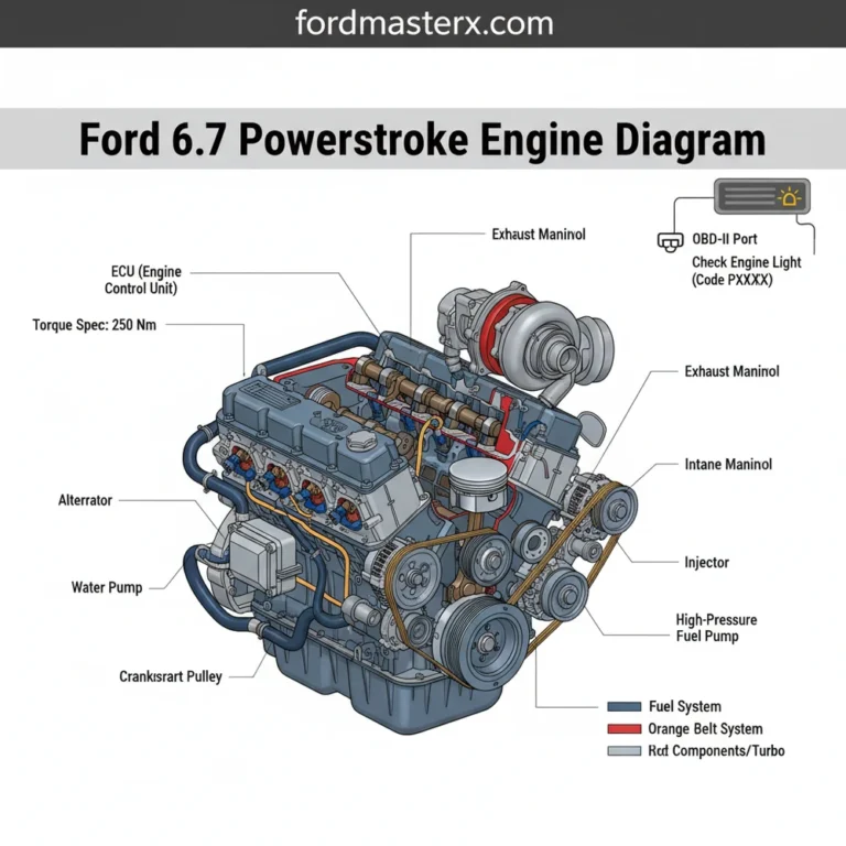
What Does the 6.2 Internal Engine Diagram Show
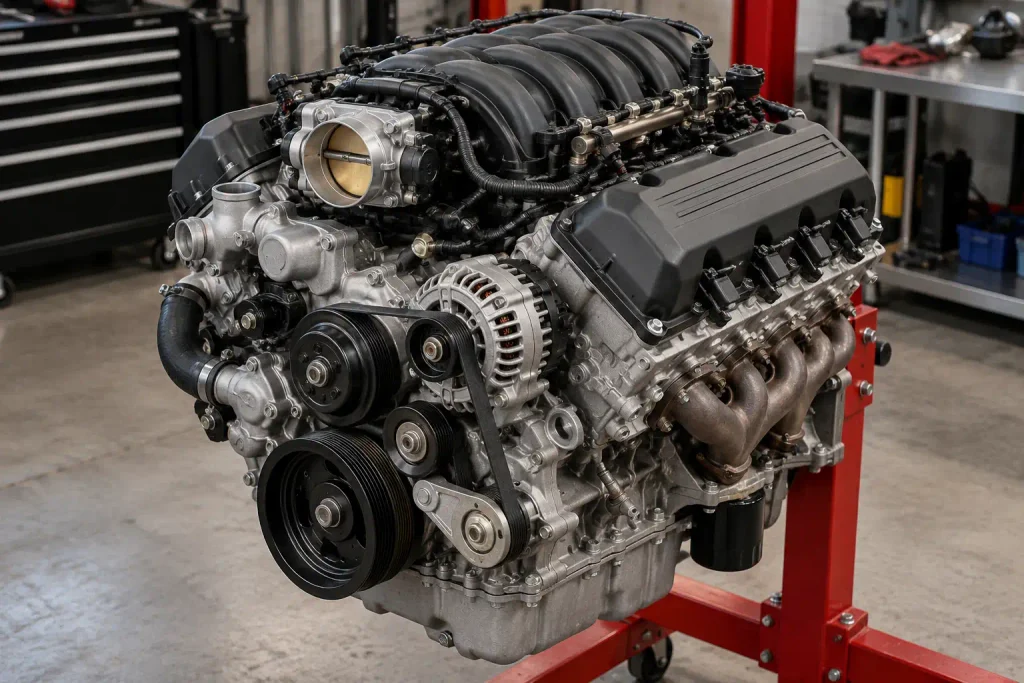
An internal engine diagram reveals the assemblies that the owner’s under-hood overview cannot show. The 6.2L Boss has a cast-iron block, aluminum cylinder heads, and a single overhead camshaft on each bank. Its valvetrain has two valves per cylinder, while the ignition system uses two spark plugs per cylinder.
The main assemblies to recognize are:
| Internal Part | Position or Function |
|---|---|
| Cylinder block | Central casting containing eight cylinder bores |
| Cylinder heads | One head above each bank, housing valves and a camshaft |
| Camshafts and phasers | At the upper part of each cylinder head, controlling valve operation and timing |
| Timing chains, guides, and tensioners | Behind the front timing cover, connecting crankshaft timing to camshaft drive |
| Crankshaft | Low in the block, converting piston motion into rotation |
| Pistons and connecting rods | Within the cylinders, connected to the crankshaft |
| Oil pump and pickup | Lubrication-system parts associated with the lower engine assembly |
| Oil pan | Lower oil-storage section beneath the block |
The accessory-drive belt at the front of the engine is not the timing chain. The external belt runs accessories; the timing chains are inside the engine behind a cover. A belt-routing image therefore cannot show how the camshafts are timed to the crankshaft.
For an exploded parts view, the 2017 F-250 6.2L Ford parts catalog identifies items such as the crankshaft pulley, oil pump, oil pickup tube, oil pan, dipstick assembly, and intake manifold. The catalog identifies parts and their relationships; it is not a substitute for the Ford workshop repair procedure.
Use the vehicle’s VIN and build information before ordering any part. A drawing may show the general assembly while the actual part or revision differs by production date, engine configuration, or equipment. That same application check matters when comparing a Raptor diagram with a Super Duty diagram.
Ford Raptor vs Super Duty Engine Bay Layout
Recommended Best Deal Products

The 6.2L gasoline V8 appeared in the first-generation F-150 Raptor and other selected F-150 configurations, as well as F-250 and F-350 Super Duty trucks. Sharing an engine family does not make their under-hood layouts interchangeable.
The 2014 F-150 6.2L under-hood overview lists nine callouts, A through I. It identifies the washer-fluid reservoir, engine-oil dipstick, brake-fluid reservoir, coolant reservoir, air-filter assembly, power-steering-fluid reservoir, power-distribution box, oil filler cap, and battery.
The 2017 Super Duty drawing lists ten callouts, A through J. Unlike the 2014 F-150 overview, it explicitly includes an automatic-transmission-fluid dipstick. The lettering also follows a different order: for example, the F-150’s callout A is the washer-fluid reservoir, while the 2017 Super Duty’s callout A is the air filter.
| Reference Truck | Number of Callouts | Distinguishing Feature |
|---|---|---|
| 2014 F-150 with 6.2L | 9 | Washer-fluid reservoir is label A; no transmission dipstick callout |
| 2017 Super Duty with 6.2L | 10 | Air filter is label A; transmission dipstick is label C |
These differences are based on the two published diagrams, not proof that a component is present or absent on every variant. A missing callout simply means that specific illustration does not identify it. Equipment and access arrangements can change between vehicles.
For a 2010 Raptor, also confirm the engine itself before using a 6.2L reference, because that model year was offered with more than one engine. Once the application is correct, reading the chosen diagram is straightforward.
How to Read the Ford 6.2 Engine Diagram
Follow three checks before using a diagram to locate a component. These checks help you avoid confusing the right engine with the wrong year, viewpoint, or assembly.
- Match the vehicle and engine. Confirm the model year, F-150 or Super Duty application, and 6.2L gasoline engine. For component replacement, identify the truck by VIN and check its original owner’s manual or a VIN-specific parts listing.
- Establish the viewpoint. Find the radiator/front and firewall/rear. For bank numbering, remember that passenger side is Bank 1 even when you are standing at the front looking into the engine compartment.
- Confirm the physical label. Match the part’s cap marking, housing, connecting hose, or wiring to the manufacturer’s drawing. If the visible component does not match, stop and find the correct manual or assembly view rather than guessing.
Use the engine bay only with the engine switched off and allowed to cool. Keep hands, clothing, and tools away from belts and fans; an electric cooling fan can operate unexpectedly. Never remove a pressurized coolant cap while the engine is hot.
A component-location diagram is for identification. It does not supply the removal sequence, tightening specifications, electrical tests, or fluid procedures needed for a repair. Choose the appropriate reference for the work you intend to do.
Which Ford 6.2 Diagram Matches Your Repair
Different drawings answer different questions. Before spending time on a long repair manual, choose the diagram that matches what you are trying to find.
| Your Task | Best Diagram or Reference | Why It Helps |
|---|---|---|
| Locate the oil filler or dipstick | Model-year under-hood overview | Shows accessible service points |
| Locate cylinder 1 or Bank 2 | Cylinder-bank numbering diagram | Establishes cylinder position and viewpoint |
| Check the ignition firing sequence | 6.2L engine specifications | Confirms the correct cylinder firing order |
| Identify the accessory belt path | Model-specific drive-belt routing diagram | Shows the pulley path, not internal engine timing |
| Identify timing-chain or camshaft parts | Engine assembly or timing-component view | Reveals parts behind the front cover |
| Verify a replacement part | VIN-filtered OEM parts catalog | Helps distinguish applicable part revisions |
If you are replacing or inspecting the external belt, use a dedicated Ford 6.2 serpentine belt routing guide together with the routing image supplied for your own truck. Do not treat a verbal description of pulley order as sufficient for installation.
Ford also publishes the 6.2L’s official engine specifications. For the 2017 Super Duty reference, they state 6,210 cm³ displacement, coil-on-plug ignition, a 9.8:1 compression ratio, and the 1-5-4-8-6-3-7-2 firing order. These are engine specifications, not torque or part-fitment instructions.
Match the question to the diagram first. Then confirm the answer against the exact vehicle before opening, testing, or replacing anything.
How to Choose Your Ford 6.2 Diagram
The most useful Ford 6.2 engine diagram is the one that matches your truck, model year, engine, and task. An under-hood drawing identifies oil and fluid service points. A cylinder-bank map locates cylinders 1 through 8. An engine-assembly drawing names internal parts that cannot be seen with the hood open.
For the 6.2L Boss V8, confirm passenger-side Bank 1, driver-side Bank 2, and the correct firing order before investigating an ignition concern. Never apply a belt-routing image to the internal timing-chain system, or assume the callout letters on a Raptor diagram mean the same thing on a Super Duty.
Open the owner’s manual for your exact year and engine. Compare its labelled figure with what you can see on the truck before proceeding with maintenance or diagnosis.
5 Common Ford 6.2 Engine Diagram Questions
Where Can I Find 6.2 Engine Diagrams
Start with the Under Hood Overview section of your Ford owner’s manual and select the 6.2L gasoline engine. That illustration identifies accessible components. For crankshaft, oil pump, timing or other internal assemblies, use a vehicle-specific exploded parts diagram instead.
Which Side Is Ford 6.2 Bank 1
Bank 1 is on the passenger side and contains cylinders 1, 2, 3, and 4, counted from front to rear. Bank 2 is on the driver side and contains cylinders 5, 6, 7, and 8. Check the radiator-facing end before counting.
How Many Spark Plugs Are in 6.2
The Ford 6.2L Boss V8 uses 16 spark plugs, two for each of its eight cylinders. This does not mean it has 16 cylinders. When tracing an ignition issue, identify the cylinder first, then the appropriate primary or secondary plug and related ignition hardware.
Are Ford Raptor and F-250 Diagrams Identical
No. The basic Boss V8 cylinder layout is consistent, but Ford’s published under-hood overviews differ between the 2014 F-150 and 2017 Super Duty. Their component callout letters also differ, so use the manual for your exact year and model rather than transferring labels between diagrams.
Where Are Ford 6.2 Internal Diagrams
Use a 6.2L-specific engine assembly or timing-component drawing in a workshop manual or OEM parts catalog. Those references show assemblies that are not visible in the owner’s under-hood illustration. Match the year, engine and VIN before choosing replacement parts or following repair instructions.