2.0 EcoBoost Ford Engine Diagram: 2026 Component Identification

The 2.0L EcoBoost engine features an aluminum block with a 10.0:1 compression ratio and direct injection. The primary components visible include the twin-scroll turbocharger, high-pressure fuel pump, and the chain-driven dual overhead camshafts. Torque specs for the main crankshaft cap bolts are 40 Nm plus 90 degrees of rotation.
📌 Key Takeaways
- The 2.0L displacement utilizes a 87.5mm bore and 83.1mm stroke configuration.
- The valve train relies on variable camshaft timing (Ti-VCT) on both intake and exhaust sides.
- Ensure cylinder head bolts are tightened to 30 Nm plus 90 degrees to prevent head gasket failure.
- The connecting rod bearings are high-load precision fit items that require specific oil clearances of 0.025-0.050mm.
- Consult a professional if the engine displays persistent misfires or loss of compression, indicating internal component wear.
The Ford 2.0 EcoBoost engine is a marvel of modern automotive engineering, blending high-pressure turbocharging with sophisticated direct injection technology. For technicians and advanced DIYers, understanding the internal layout via a comprehensive Ford 2.0 EcoBoost engine diagram is essential for performing accurate diagnostics and high-precision repairs. This power plant, found in platforms ranging from the Focus ST to the Edge and Escape, relies on a complex synchronization between its forced-induction subsystems and its tightly controlled valvetrain. Navigating the spatial relationship between the engine block, the turbocharger assembly, and the high-pressure fuel management system is the first step toward mastering this versatile four-cylinder architecture.

Prime for Young Adults — 6 Months Free
Students and 18–24s get six months of Prime free, then half price.
Start 6 Months Free As an Amazon Associate I earn from qualifying purchases.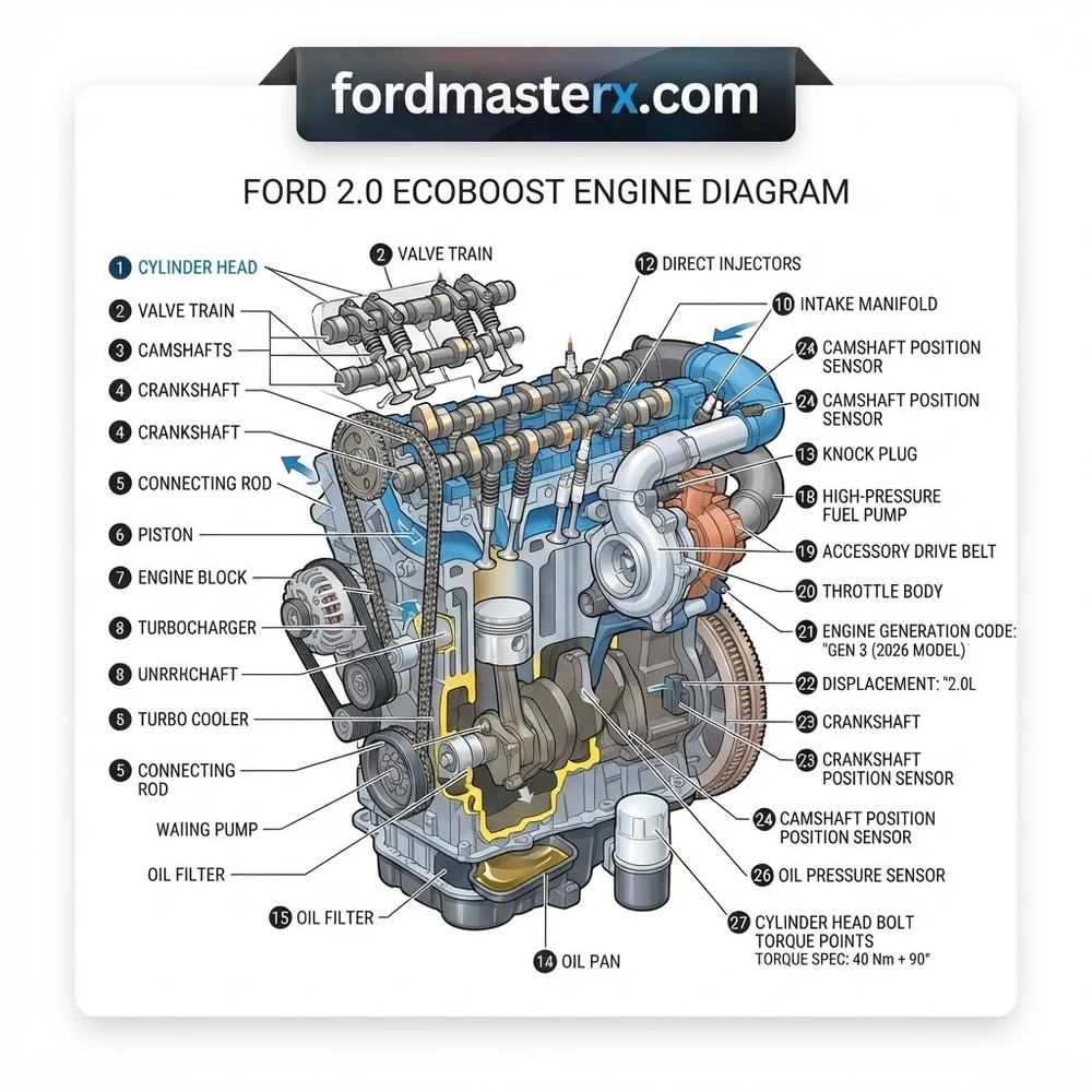
Ford 2.0 EcoBoost Engine Diagram: Component Identification Guide
Recommended Best Deal Products


When viewing a high-resolution Ford 2.0 EcoBoost engine diagram, the first task is identifying the major subsystems mounted to the engine block. The 2.0 EcoBoost utilizes a modular design that separates the high-stress rotational components from the complex peripheral management systems.
The turbocharger assembly is typically mounted to the rear of the exhaust manifold. In a technical teardown, the diagram highlights the feed and return lines for both oil and coolant. Proper lubrication here is non-negotiable; as indicated by the service manual, restricted oil feed lines are the leading cause of premature turbo bearing failure. Beneath the turbo, you will locate the intercooler piping—often the first area to check when diagnosing a loss of boost pressure or a “low power” code.
Mounted to the cylinder head, the high-pressure fuel pump (HPFP) is driven by a specialized lobe on the intake camshaft. You must observe the orientation of the fuel lines in the diagram carefully; these operate at extremely high pressures—sometimes exceeding 2,000 PSI. Never attempt to loosen these fittings while the engine is hot or pressurized.
The direct injection injectors are seated directly into the combustion chambers. Unlike port-injected systems, these components are highly sensitive to carbon buildup. The Ford 2.0 EcoBoost engine diagram clearly illustrates the path of the fuel rail, which connects the HPFP to the four individual injectors. When inspecting these, verify the integrity of the O-rings and Teflon seals; failure here results in crankcase dilution, which can rapidly accelerate wear on the connecting rod bearings and crankshaft journals.
Finally, the cooling system layout, which is integrated into the engine block and cylinder head, features an electronically controlled thermostat and a dedicated water pump drive. Familiarizing yourself with these paths is critical for performing coolant flushes or water pump replacements, as air pockets in this specific cooling loop are notorious for causing localized overheating and subsequent head gasket degradation.
Ford 2.0 EcoBoost Generations and Technical Specification Table

Discrepancies in part sourcing often stem from the evolution of the 2.0 EcoBoost across its production life. Technicians must distinguish between the early Gen 1 units and the revised Gen 2 engines, which introduced significant changes to the cylinder head architecture and the fuel delivery system.
| Generation | Production Years | Key Characteristic |
|---|---|---|
| Gen 1 (2.0L) | 2010–2016 | Integrated manifold/turbo; standard steel block. |
| Gen 2 (Twin-Scroll) | 2015–Present | Twin-scroll turbo; updated valve train; improved HPFP. |
| 2.3L Variant | 2015–Present | Larger bore/stroke; different rod architecture. |
Always verify the engine code on the block stamp before ordering internals such as pistons or connecting rods. While Gen 1 and Gen 2 share basic geometry, the piston dish depth and ring land thickness vary between these iterations, which can lead to catastrophic failure if parts are mismatched.
Internal Valve Train and Cylinder Head Architecture
Recommended Best Deal Products

The operational heart of the Ford 2.0 EcoBoost resides in the precise timing between the camshaft and the crankshaft. The valve train uses a double overhead cam (DOHC) setup featuring Variable Camshaft Timing (VCT) phasers on both intake and exhaust sides. These phasers adjust the valve overlap to optimize power delivery and emissions across the RPM band.
The cylinder head contains the four-valve-per-cylinder geometry. When performing a timing job, you must utilize the factory-specified locking tools to fix the camshafts in position while the crankshaft is set at Top Dead Center (TDC). Deviating from these OEM procedures can lead to valve-to-piston contact, destroying the engine block’s internals.

Audible — Listen Free for 30 Days
One free credit a month and thousands of titles included.
Listen Free for 30 Days As an Amazon Associate I earn from qualifying purchases.Connecting rod strength and piston cooling are also critical aspects of the 2.0 EcoBoost architecture. The engine utilizes oil-jet squirters mounted in the engine block to provide a consistent stream of lubricant to the underside of the pistons. This heat management is essential under high-boost scenarios. If you are disassembling the short block, ensure that the connecting rod end caps are matched to their respective rods—they are fracture-split, meaning they are a unique, non-interchangeable fit.
The crankshaft is supported by five main bearings, with the oil pan assembly acting as a structural member in many longitudinal applications. The oil pan must be sealed with precision, as high-pressure crankcase gases can bypass insufficient seals, leading to excessive blow-by and oil consumption.
Crankshaft Main Bearing Bolt Torque: 30 Nm + 90 degrees. Always replace these Torque-to-Yield (TTY) bolts during any rebuild procedure to ensure adequate clamping force on the main caps.
Common Ford 2.0 EcoBoost Engine Diagram Failure Points
Even with meticulous maintenance, certain components in the Ford 2.0 EcoBoost ecosystem exhibit predictable wear patterns. Identifying these before they cascade into complete engine failure is the hallmark of a professional technician.
Turbocharger Wastegate Actuator: The linkage on the wastegate is prone to sticking due to heat cycling. When this happens, the Powertrain Control Module (PCM) detects an over-boost or under-boost condition, triggering a limp mode.
PCM Calibration and Sensor Feedback: The PCM relies on a complex array of inputs, including the Mass Air Flow (MAF) sensor and Manifold Absolute Pressure (MAP) sensors. A faulty sensor often mimics mechanical engine issues, so always verify sensor data via a scanner before internal engine disassembly.
Coolant Intrusion: A known failure point in early Gen 1 engine blocks involves the coolant passages between the cylinders. If you observe coolant loss without an external leak, perform a pressure test on the cooling system and use a borescope to inspect for signs of coolant inside the cylinders.
High-Pressure Fuel Pump Cam Follower: While the 2.0 EcoBoost is less prone to this than its 2.0L predecessors, the HPFP follower must still be inspected for pitting. A collapsed follower will damage the camshaft lobe, creating metal debris that can circulate through the cylinder head and block.
* Oil Pan and Gasket Integrity: The oil pan on this engine is highly sensitive to impact. Since the oil pickup tube sits close to the bottom of the pan, even a minor dent can restrict oil flow to the crankshaft, causing rapid bearing failure.
Never reuse head bolts. These are designed for a single use and are stretched to their yield point during installation. Reusing them can result in an improper seal at the cylinder head, leading to cooling system contamination and potential combustion chamber pressure loss.
Ford 2.0 EcoBoost Engine Diagram Questions Answered
Is it possible to rebuild the engine block with aftermarket forged connecting rods?
Yes, however, ensure that the crankshaft journals are polished to OEM specifications first. Forged rods usually require greater clearance than factory cast units. You must perform a plastigage measurement on every rod journal to verify that oil pressure will remain within the 40–60 PSI range at operating temperature.
What is the recommended interval for inspecting the valve train components?
While Ford does not provide a specific interval for internal valve train inspection, we recommend a compression and leak-down test every 60,000 miles. This will help you detect any degradation in the cylinder head seals or piston ring sealing, which is vital before any major performance tuning is applied.
Can the oil pan be removed while the engine is in the vehicle?
In most chassis configurations (such as the Escape or Fusion), the oil pan removal is obstructed by the subframe. You will likely need to support the engine from above and partially lower the subframe to gain the necessary clearance. Always replace the oil pan gasket and bolts when performing this service.
Why does my scan tool report a P0016 code, and how does the diagram help?
A P0016 code indicates a correlation error between the crankshaft and camshaft position sensors. By using the Ford 2.0 EcoBoost engine diagram, you can trace the wiring harness from these sensors back to the PCM to check for electrical continuity or signal interference. If wiring is sound, the issue usually points to a stretched timing chain or a failed VCT phaser.
Audible Premium Plus — Annual Membership
12 audiobook credits up front, plus the full Audible catalogue.
See Annual Plans As an Amazon Associate I earn from qualifying purchases.What role does the crankshaft position sensor play in the overall engine management?
The crankshaft position sensor provides the PCM with the exact RPM and position of the crankshaft journals. Without this data, the PCM cannot accurately time the spark or the direct injection pulses, resulting in a “no start” condition or severe misfiring. Always ensure the sensor gap is calibrated according to the service manual if the engine block has been machined.
Step-by-Step Guide to Understanding the Ford 2.0 Ecoboost Engine Diagram
Identify – Locate the VIN and engine serial number on the block casting to ensure your manual matches the specific 2.0L variant.
Locate – Remove the decorative engine cover to expose the cylinder head, fuel rail, and valve train components for clear visibility.
Reference – Use the diagram to map the vacuum lines and electrical connectors before disconnecting any sensors to avoid routing errors.
Connect/Route – Route the serpentine belt according to the diagram, ensuring the tensioner is fully retracted to clear the crankshaft pulley.
Verify – Check all torque values on the connecting rod and cylinder head bolts using a calibrated wrench to meet factory specifications.
Troubleshoot – If the engine fails to start, verify the camshaft position sensor alignment using the provided pinout diagram to ensure ignition timing.