2013 Ford Fusion Fuse Box Diagram: Complete Fuse and Relay Charts

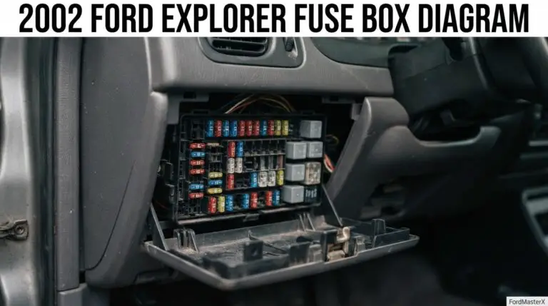
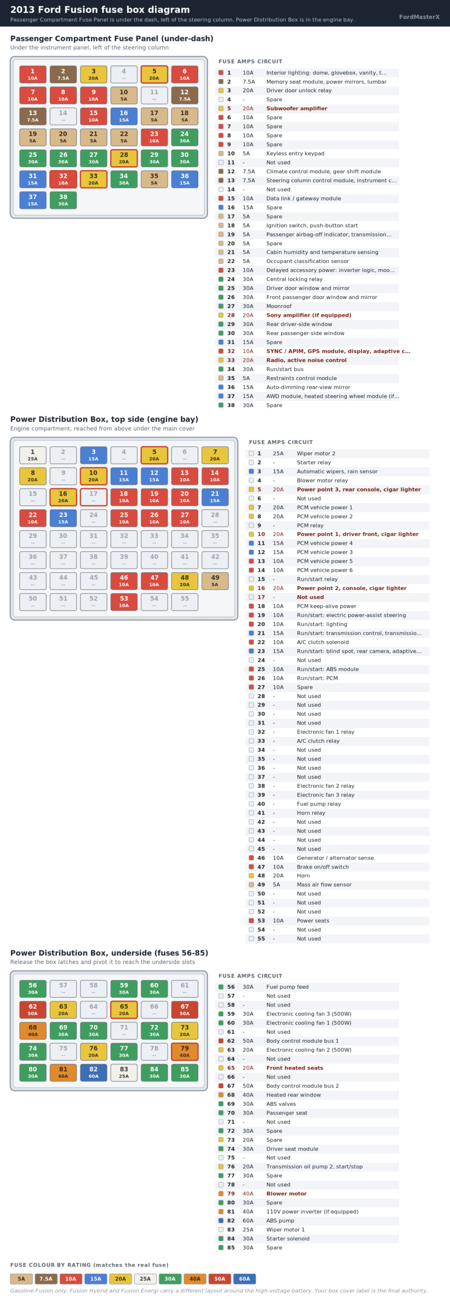
Your 2013 Ford Fusion has two fuse boxes. The Passenger Compartment Fuse Panel is under the dash, left of the steering column. The Power Distribution Box is in the engine bay.
The cigarette lighter and console power points are fuses 5, 10 and 16, all 20A, inside the Power Distribution Box.
What Most Fuse Guides Get Wrong About The 2013 Fusion
Recommended Best Deal Products


The 2013 Fusion is an all-new 2nd generation car, Ford’s CD4 platform, built 2013 to 2020. It shares nothing with the 1st generation Fusion built 2006 to 2012 on the Mazda6-based CD3 platform. No fuse number carries across that line, even though both cars share a nameplate.
Several combined “2013-2021 Fusion” fuse tables also get specific 2013 positions wrong. Fuse 11 and fuse 14 in the interior panel are factory-unused on a 2013 Fusion.
One widely mirrored table assigns them a “general safety module” and an “extended power module.” Those are later-year assignments, or ones that belong to the Lincoln MKZ, which shares this platform.
Fuse 16 in the interior panel is a plain 15A spare on a 2013 Fusion. It becomes the child lock and decklid release relay starting with the 2015 model year.
Fuse 20 is a 5A spare in 2013, not the headlamp control module some combined tables list. A source scoped to the 2013 model year specifically confirms this.
Fuse 17 in the Power Distribution Box top side is unused in 2013. It becomes a 20A cargo area power outlet in later years of the same generation. Confirm your exact model year before trusting any single combined-range table on this car.
This chart covers the gasoline Fusion. The Fusion Hybrid and Fusion Energi plug-in use a different layout around the high-voltage battery. Neither is covered here.
Where Is The Fuse Box On A 2013 Ford Fusion?
The Passenger Compartment Fuse Panel is under the instrument panel, to the left of the steering column. A trim panel covers it and pries off by hand.
The Power Distribution Box is in the engine bay. Its top side, fuses 1 through 55, sits under the main cover you can see with the hood up.
The underside, fuses 56 through 85, takes more work. Release the two side latches and pivot the whole box out of its cradle to reach it.
2013 Ford Fusion Passenger Compartment Fuse Panel: Complete Chart
Recommended Best Deal Products


This is every position in the under-dash panel, including the spares. A “Spare” slot is an empty position Ford leaves open for optional equipment. “Not used” means the position is reserved and carries no fuse at all this year.
| Fuse | Rating | Circuit |
|---|---|---|
| 1 | 10A | Interior lighting: dome, glovebox, vanity, trunk lamp, battery saver relay |
| 2 | 7.5A | Memory seat module, power mirrors, lumbar |
| 3 | 20A | Driver door unlock relay |
| 4 | – | Spare |
| 5 | 20A | Subwoofer amplifier |
| 6 | 10A | Spare |
| 7 | 10A | Spare |
| 8 | 10A | Spare |
| 9 | 10A | Spare |
| 10 | 5A | Keyless entry keypad |
| 11 | – | Not used |
| 12 | 7.5A | Climate control module, gear shift module |
| 13 | 7.5A | Steering column control module, instrument cluster, data link logic |
| 14 | – | Not used |
| 15 | 10A | Data link / gateway module |
| 16 | 15A | Spare |
| 17 | 5A | Spare |
| 18 | 5A | Ignition switch, push-button start |
| 19 | 5A | Passenger airbag-off indicator, transmission range sensor |
| 20 | 5A | Spare |
| 21 | 5A | Cabin humidity and temperature sensing |
| 22 | 5A | Occupant classification sensor |
| 23 | 10A | Delayed accessory power: inverter logic, moonroof logic |
| 24 | 30A | Central locking relay |
| 25 | 30A | Driver door window and mirror |
| 26 | 30A | Front passenger door window and mirror |
| 27 | 30A | Moonroof |
| 28 | 20A | Sony amplifier (if equipped) |
| 29 | 30A | Rear driver-side window |
| 30 | 30A | Rear passenger-side window |
| 31 | 15A | Spare |
| 32 | 10A | SYNC / APIM, GPS module, display, adaptive cruise, RF receiver |
| 33 | 20A | Radio, active noise control |
| 34 | 30A | Run/start bus |
| 35 | 5A | Restraints control module |
| 36 | 15A | Auto-dimming rear-view mirror |
| 37 | 15A | AWD module, heated steering wheel module (if equipped) |
| 38 | 30A | Spare |
2013 Ford Fusion Power Distribution Box: Complete Fuse And Relay Chart
This is every position in the engine-bay box, split by the two sides you physically access. Relay-only slots carry no amperage rating.
Top side, fuses 1 to 55:
| Fuse | Rating | Circuit |
|---|---|---|
| 1 | 25A | Wiper motor 2 |
| 2 | – | Starter relay |
| 3 | 15A | Automatic wipers, rain sensor |
| 4 | – | Blower motor relay |
| 5 | 20A | Power point 3, rear console, cigar lighter |
| 6 | – | Not used |
| 7 | 20A | PCM vehicle power 1 |
| 8 | 20A | PCM vehicle power 2 |
| 9 | – | PCM relay |
| 10 | 20A | Power point 1, driver front, cigar lighter |
| 11 | 15A | PCM vehicle power 4 |
| 12 | 15A | PCM vehicle power 3 |
| 13 | 10A | PCM vehicle power 5 |
| 14 | 10A | PCM vehicle power 6 |
| 15 | – | Run/start relay |
| 16 | 20A | Power point 2, console, cigar lighter |
| 17 | – | Not used |
| 18 | 10A | PCM keep-alive power |
| 19 | 10A | Run/start: electric power-assist steering |
| 20 | 10A | Run/start: lighting |
| 21 | 15A | Run/start: transmission control, transmission oil pump start/stop |
| 22 | 10A | A/C clutch solenoid |
| 23 | 15A | Run/start: blind spot, rear camera, adaptive cruise, head-up display |
| 24 | – | Not used |
| 25 | 10A | Run/start: ABS module |
| 26 | 10A | Run/start: PCM |
| 27 | 10A | Spare |
| 28-31 | – | Not used |
| 32 | – | Electronic fan 1 relay |
| 33 | – | A/C clutch relay |
| 34-37 | – | Not used |
| 38 | – | Electronic fan 2 relay |
| 39 | – | Electronic fan 3 relay |
| 40 | – | Fuel pump relay |
| 41 | – | Horn relay |
| 42-45 | – | Not used |
| 46 | 10A | Generator / alternator sense |
| 47 | 10A | Brake on/off switch |
| 48 | 20A | Horn |
| 49 | 5A | Mass air flow sensor |
| 50-52 | – | Not used |
| 53 | 10A | Power seats |
| 54-55 | – | Not used |
Underside, fuses 56 to 85:
| Fuse | Rating | Circuit |
|---|---|---|
| 56 | 30A | Fuel pump feed |
| 57-58 | – | Not used |
| 59 | 30A | Electronic cooling fan 3 (500W) |
| 60 | 30A | Electronic cooling fan 1 (500W) |
| 61 | – | Not used |
| 62 | 50A | Body control module bus 1 |
| 63 | 20A | Electronic cooling fan 2 (500W) |
| 64 | – | Not used |
| 65 | 20A | Front heated seats |
| 66 | – | Not used |
| 67 | 50A | Body control module bus 2 |
| 68 | 40A | Heated rear window |
| 69 | 30A | ABS valves |
| 70 | 30A | Passenger seat |
| 71 | – | Not used |
| 72 | 30A | Spare |
| 73 | 20A | Spare |
| 74 | 30A | Driver seat module |
| 75 | – | Not used |
| 76 | 20A | Transmission oil pump 2, start/stop |
| 77 | 30A | Spare |
| 78 | – | Not used |
| 79 | 40A | Blower motor |
| 80 | 30A | Spare |
| 81 | 40A | 110V power inverter (if equipped) |
| 82 | 60A | ABS pump |
| 83 | 25A | Wiper motor 1 |
| 84 | 30A | Starter solenoid |
| 85 | 30A | Spare |
Which Fuse Is The Cigarette Lighter Or Power Outlet On A 2013 Fusion?
Recommended Best Deal Products


Three fuses in the Power Distribution Box cover the power points, all rated 20A. Fuse 10 runs the driver-front outlet. Fuse 16 runs the console outlet, and fuse 5 the rear console outlet.
All three are labelled cigar lighter circuits by Ford. If one outlet is dead and the others work, the fault is more likely the outlet than the fuse.
Which Fuse Is The Radio, SYNC Or Amplifier?
Fuse 33 (20A) in the interior panel runs the radio and active noise control. Fuse 32 (10A) runs SYNC, the APIM, the GPS module, the display and the RF receiver.
The base subwoofer amplifier runs on fuse 5 (20A). A Fusion with the Sony audio upgrade adds fuse 28 (20A) for that amplifier.
My… Doesn’t Work: Symptom To Fuse
| Symptom | Check these fuses first |
|---|---|
| No power at any cigarette lighter or console outlet | 5, 10, 16 (Power Distribution Box) |
| Radio, SYNC or screen is dead | 32, 33 (Passenger Compartment panel) |
| Subwoofer or Sony amplifier silent | 5, 28 (Passenger Compartment panel) |
| Horn does not sound | 48 and relay 41 (Power Distribution Box) |
| Heated seats do not warm | 65 (Power Distribution Box, underside) |
| Moonroof will not move | 27 (Passenger Compartment panel) |
| Power windows are dead | 25, 26, 29, 30 (Passenger Compartment panel) |
| A/C compressor will not engage | 22 and relay 33 (Power Distribution Box) |
| Engine will not crank | 84 (Power Distribution Box, underside), relay 2 and relay 15 (top side) |
| Wipers are dead or stuck | 1, 3, 83 (Power Distribution Box) |
| Blower motor has no airflow at any speed | 79 (Power Distribution Box, underside) and relay 4 (top side) |
| Rear window defroster does not clear | 68 (Power Distribution Box, underside) |
How Do You Know If A Fuse Is Blown?
Pull the suspect fuse straight out with a fuse puller, the plastic tool clipped inside the box cover. Hold it up to the light.
A good mini fuse shows one continuous metal strip. A blown one shows a gap or a dark, melted spot in that strip.
A multimeter set to continuity or ohms gives a more certain answer than eyeballing it. That matters most on the underside positions, where a hairline break is hard to see. Touch a probe to each end of the fuse.
Continuity means the fuse is good. No reading at all means it is blown.
Keep a small assortment of mini fuses in the glovebox. A fuse assortment kit covering the common mini sizes fits this box and costs less than one dealer visit.
Any brand meeting the ATO/ATC mini fuse standard works. A basic digital multimeter earns its place in the glovebox too, for the same continuity check.
Why Does The Same Fuse Keep Blowing?
A fuse that blows once from a momentary short is normal. One that blows again within a week means the short is still there. Replacing it again just delays the next failure.
A chafed wiring harness or a corroded ground strap are the common culprits on this generation. A failing module can also draw more current than its fuse allows. None of those show up from staring at the fuse box.
You need to read live current draw with a scan tool. Our Ford diagnostic tool comparison covers what actually works for pulling live data on these cars.
One note on the PCM fuses: 7, 8, 11 through 14, 18 and 26. Pulling any of them, or disconnecting the battery, erases the PCM’s learned idle and shift settings.
A drive cycle after the repair lets it relearn them.
What Changed Across The 2nd Generation Fusion Fuse Panel?
If you have a 2011 or 2012 Fusion instead, stop here. That is the 1st generation, a different platform with a different fuse panel in a different location. Our 2011 and 2012 Ford Fusion fuse box diagrams cover that generation, and no fuse number here applies there.
Within this generation, Ford revised several interior panel positions for the 2015 facelift. See the section above for the four positions that changed.
If your Fusion is a 2015 or newer, treat those four positions as different from what is shown here.
Quick Reference: The 2013 Fusion Fuses You Will Look Up Most
| Need | Fuse | Rating | Box |
|---|---|---|---|
| Cigarette lighter / console power points | 5, 10, 16 | 20A | Power Distribution Box |
| Radio | 33 | 20A | Passenger Compartment panel |
| SYNC / APIM / GPS | 32 | 10A | Passenger Compartment panel |
| Subwoofer amplifier | 5 | 20A | Passenger Compartment panel |
| Horn | 48 | 20A | Power Distribution Box |
| Starter solenoid | 84 | 30A | Power Distribution Box, underside |
| Fuel pump | 56 | 30A | Power Distribution Box, underside |
| ABS pump | 82 | 60A | Power Distribution Box, underside |
| Heated front seats | 65 | 20A | Power Distribution Box, underside |
| Blower motor | 79 | 40A | Power Distribution Box, underside |
| Heated rear window | 68 | 40A | Power Distribution Box, underside |
| Moonroof | 27 | 30A | Passenger Compartment panel |
Ford does not publish one document listing every trim variation for both boxes together. The label on the inside of each box cover is the final authority for your specific Fusion. That matters most if a previous owner has already swapped a fuse rating.