
Ford Radius Arm Bushing Diagram: 2026 Component Breakdown

The radius arm bushing system consists of a polyurethane or rubber bushing sandwiched between the radius arm eyelet and the chassis bracket. Secure the assembly using the provided nut and bolt. Ensure the flanged side of the bushing faces the rear bracket to prevent lateral movement and maintain proper suspension alignment.
📌 Key Takeaways
- Torque the main radius arm nut to specification, typically between 150-220 ft-lbs depending on the specific Ford model year.
- The bushing acts as a critical vibration dampener in the suspension system configuration.
- Always replace hardware if rusted; reuse of damaged bolts can lead to catastrophic suspension failure.
- Common failure involves dry-rot of the rubber structure, leading to audible clunking during braking.
- Consult a professional if the chassis bracket shows signs of stress fractures or excessive metal fatigue.
The Ford Twin-I-Beam and solid axle suspension systems rely heavily on the radius arm to maintain longitudinal stability. A clear understanding of the Ford radius arm bushing diagram is essential for any technician tasked with restoring handling precision and axle alignment. These bushings act as the primary interface between the chassis and the axle assembly, bearing the brunt of braking forces and road impacts. When these components degrade, the resulting shift in caster angle can lead to erratic steering, uneven tire wear, and dangerous chassis vibration. This guide provides an in-depth technical analysis of the assembly, configuration, and service procedures required to maintain factory-spec suspension geometry across heavy-duty and light-duty Ford trucks.
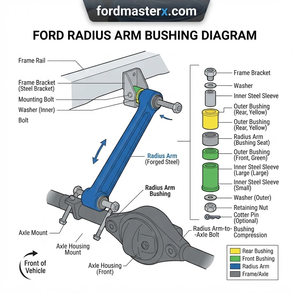
Ford Radius Arm Bushing Diagram: Anatomy of the Assembly


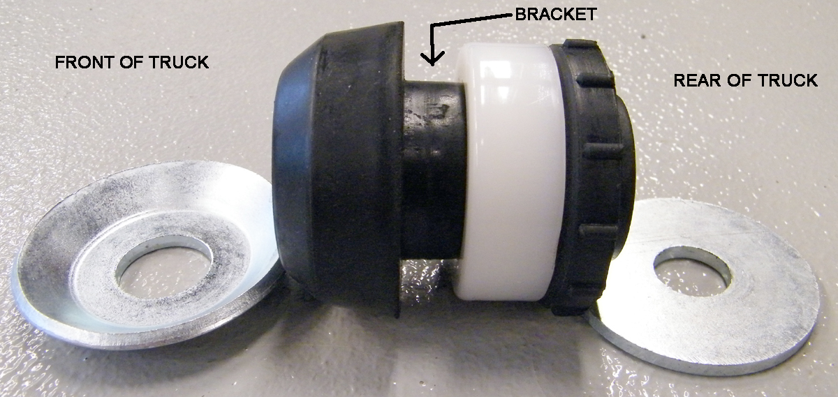
The radius arm configuration is engineered to anchor the axle to the frame while allowing for vertical articulation. By analyzing the Ford radius arm bushing diagram, a technician can identify the specific arrangement of the high-durometer components required to isolate road vibration from the frame. At the core of the assembly is the radius arm stud, which extends from the forged radius arm and passes through the frame-mounted bracket.


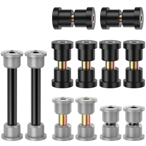
The assembly relies on a two-piece bushing setup. These bushings are usually manufactured from compressed rubber or high-performance polyurethane. The diagram illustrates a split design: one bushing half sits on the outboard side of the frame bracket, while the other sits on the inboard side. Proper orientation is non-negotiable; the tapered or flanged sections must seat flush within the bracket apertures to prevent lateral movement of the radius arm.
Supporting these bushings are heavy-gauge steel retainer washers. These washers act as a preload plate, ensuring that the nut torque is distributed evenly across the bushing face. Without these retainers, the radius arm stud would quickly erode the bushing material, leading to premature failure. The final securing component is the radius arm nut—a self-locking or castle-style fastener that maintains the necessary compression on the bushing stack.
For mechanics, understanding the “stack-up” is critical. The assembly order generally proceeds from the axle forward: the radius arm end, the first bushing half, the frame bracket, the second bushing half, the outer retainer washer, and the locking nut. If the diagram shows a variation—such as a different washer thickness for high-payload models—it is usually to accommodate increased suspension travel or greater static load. Technicians should always verify the part configuration against the specific model year, as Ford transitioned between various rubber durometers and mounting bracket depths throughout the production cycles of the F-Series and Bronco platforms.
Note that aftermarket polyurethane bushings often lack the compliance of OEM-style rubber. While they improve steering feedback and caster stability, they transmit significantly more road harshness and cabin noise to the frame rail.
How to Diagnose Faulty Ford Radius Arm Bushing Symptoms


Suspension geometry is intrinsically linked to the integrity of these bushings. A compromised bushing setup directly impacts the caster angle, which is the tilt of the steering axis. When the rubber or polyurethane deteriorates, the radius arm moves freely within the bracket, causing the axle to shift fore and aft during braking or acceleration.
The most common symptoms include a distinct “clunk” audible from the front end when transitioning from braking to acceleration. This indicates the radius arm is hitting the bracket because the bushing material has lost its structural resilience. Furthermore, if you observe the I-beam axle under load, a visual inspection may reveal excessive daylight between the bushing and the steel washer.


Technicians should evaluate the system using the following diagnostic checklist:
- Asymmetrical Tire Wear: Rapid inner or outer edge wear often stems from the axle “walking” forward or backward due to bushing play, which alters the camber and toe settings dynamically.
- Braking Instability: If the vehicle pulls sharply to one side only when the brakes are applied, it is a hallmark sign that the radius arm is shifting on the side with the failed bushing.
- Steering Wander: At highway speeds, if the vehicle feels like it is “hunting” for the road, the lack of caster stability caused by the worn bushing is a likely culprit.
- Visual Bracket Erosion: Inspect the frame bracket for metallic scuffing. If the radius arm metal has touched the frame, the bushing has completely failed, and you may need to check for frame bracket deformation.
Addressing these issues early prevents damage to the radius arm stud threads or the bracket itself. If the bracket is ovalized or cracked, simple bushing replacement will not restore structural integrity, and the mounting point may require reinforcement or replacement.
Never attempt to heat the radius arm to facilitate removal. Heating these components can compromise the heat-treatment of the forged steel, leading to catastrophic failure of the suspension arm under load.
Step-by-Step Ford Radius Arm Bushing Installation Procedure


Replacing these bushings requires a systematic approach to ensure the radius arm is correctly aligned with the mounting bracket. Before starting, ensure the vehicle is supported by jack stands on the frame rails, allowing the front suspension to reach full droop.
1. Relieve Tension: Ensure the vehicle is secure and the axle is properly supported. Disconnect the sway bar end links to allow for maximum vertical travel of the radius arm assembly if necessary.
2. Remove the Radius Arm Nut: Utilize a high-torque impact wrench or a long-handled breaker bar to remove the large retaining nut from the radius arm stud. If the nut is seized, apply a penetrating lubricant and allow it to soak.
3. Clearance Strategy: To gain enough clearance to remove the old bushings, you may need to loosen the coil spring or the axle pivot bolt. Carefully move the radius arm stud out of the frame bracket hole.
4. Component Extraction: Remove the old, hardened, or cracked rubber bushings. Use a wire brush to clean the radius arm stud and the inner face of the frame bracket. Any debris left on the bracket surface will cause the new bushings to seat improperly.
5. Install New Bushings: Lubricate the new bushings with a silicone-based grease, especially if using polyurethane. Slide the first half onto the stud from the inboard side, then slide the arm into the frame bracket.
6. Alignment and Reassembly: Install the outboard bushing half and the steel retainer washer. Thread the radius arm nut onto the stud. Ensure the stud is centered in the bracket hole. If the stud is not centered, the suspension geometry will be permanently skewed.
7. Torque Specification: Tighten the radius arm nut to the manufacturer’s specified torque. It is vital to use a calibrated torque wrench. Over-tightening can crush the bushings, while under-tightening will lead to premature “walk” and hardware failure.
8. Final Alignment: Once the installation is complete, verify the front-end alignment. A replacement of these bushings almost always necessitates a professional alignment to reset caster and toe, as the new bushing thickness can alter the original geometry significantly.


Always replace the radius arm nut with a new OEM-equivalent locking nut. These are single-use fasteners designed to deform slightly to lock onto the stud threads.
Ford Radius Arm Bushing Maintenance and Torque Specs
Proper maintenance involves routine visual inspections every 15,000 miles, particularly for vehicles used in towing or off-road conditions. When performing an oil change, take a moment to look at the bushing stack-up. If you see signs of “mushrooming” or cracking around the edges, the component is nearing the end of its service life.
The following table provides general reference torque values for common Ford light truck applications. Please cross-reference these with your specific service manual, as hardware diameters can vary based on Gross Vehicle Weight Rating (GVWR).
| Vehicle Model/Series | Bushing Material | Required Torque (ft-lbs) |
|---|---|---|
| F-150 (1980–1996) | Rubber (OEM) | 180–220 |
| F-250/F-350 (Pre-1998) | Polyurethane | 200–250 |
| Bronco (Full Size) | Rubber (OEM) | 180–220 |
| E-Series Vans | Rubber (OEM) | 200–240 |
Adhering to these specifications is crucial. The high torque values are required because the radius arm experiences significant leverage; any slack in the assembly is magnified at the tires. Furthermore, if you are upgrading to polyurethane, be aware that these materials do not compress like rubber. You must be precise with the nut positioning to prevent binding during suspension articulation. Always consult the specific technical blueprint for your chassis to ensure you are not exceeding the tensile strength of the radius arm stud.


Ford Radius Arm Bushing Diagram Questions Answered
Is it possible to replace the bushings without removing the entire radius arm?
Yes, most Ford radius arm bushing designs allow for in-situ replacement. By supporting the axle and disconnecting the sway bar, you can usually manipulate the radius arm stud enough to slide the old bushings off and install the new ones without full removal of the arm from the axle beam.
How can I tell if I need a full radius arm replacement instead of just the bushings?



If the radius arm stud is bent, the threads are stripped, or the mounting hole in the frame bracket has become elongated (ovalized) beyond the reach of the bushing lip, a simple bushing kit will not suffice. If the arm itself shows signs of fatigue cracks, replace the entire component for safety.
Why do aftermarket polyurethane bushings often squeak?


Polyurethane is a harder material than rubber and creates more friction during the compression cycles of the suspension. Without the liberal application of a high-tack, marine-grade grease during installation, the bushings will dry-cycle against the steel washers, resulting in an audible squeaking or groaning noise.
Does the Ford radius arm bushing diagram vary between 2WD and 4WD models?


While the fundamental concept remains the same, the geometry, length of the radius arm, and the specific shape of the bushing can vary significantly between 2WD and 4WD versions of the same truck. Always match your parts using the VIN or axle code found on the door placard to ensure the correct radius arm bushing configuration.


