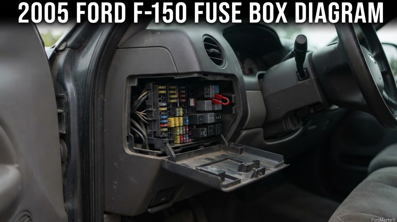
2005 Ford F-150 Fuse Box Diagram: Every Fuse and Amp Rating

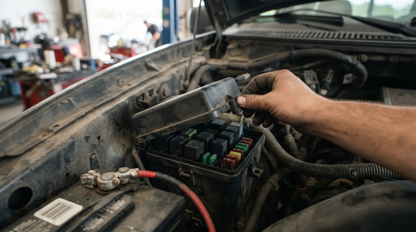
Your 2005 F-150 has one main fuse box and one small relay box. The passenger compartment panel, on the right side of the instrument panel, holds every mini and cartridge fuse. The cigar lighter and diagnostic connector share fuse 41, rated 20A.
Where are the fuse boxes on a 2005 F-150?
Recommended Best Deal Products


This truck splits its electrical protection two ways, and one box does almost all the work.

Prime for Young Adults — 6 Months Free
Students and 18–24s get six months of Prime free, then half price.
Start 6 Months Free As an Amazon Associate I earn from qualifying purchases.Passenger compartment fuse panel. Behind a cover on the right side of the instrument panel. Ford calls this the power distribution box on this generation, even though it lives in the cab. It holds 42 mini fuses, 19 cartridge fuses, and one circuit breaker.
Auxiliary relay box. A separate, much smaller box in the engine compartment on the left fender, near the battery. It carries one 5A fuse for clockspring illumination plus the relays for 4×4 engagement and daytime running lamps.
If your truck is a 1997 to 2003 model, stop here. That generation puts the cab panel on the driver side, by the brake pedal. It numbers the cigar lighter fuse 3, not 41. Our 2002 Ford F-150 fuse box diagram covers that earlier truck.
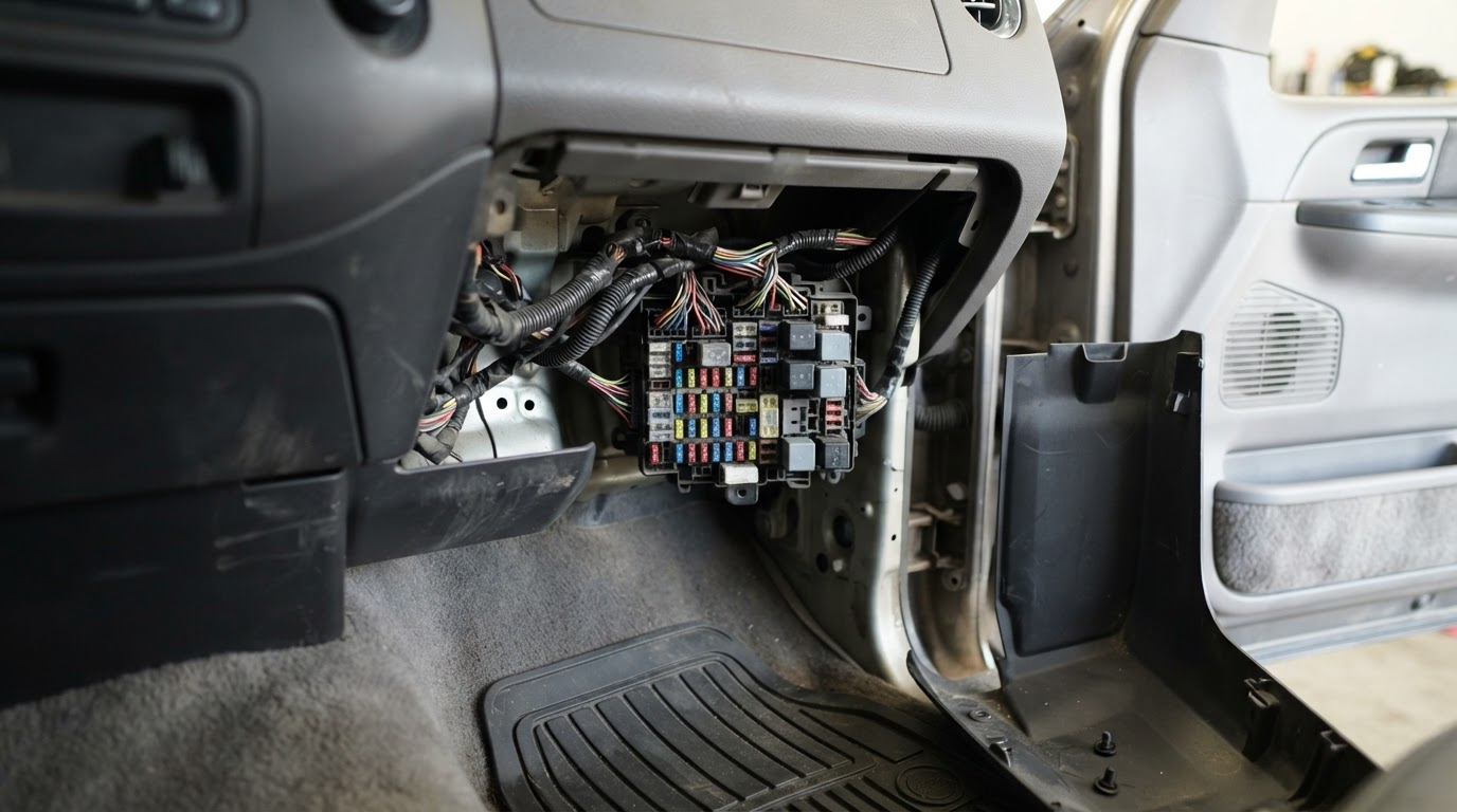
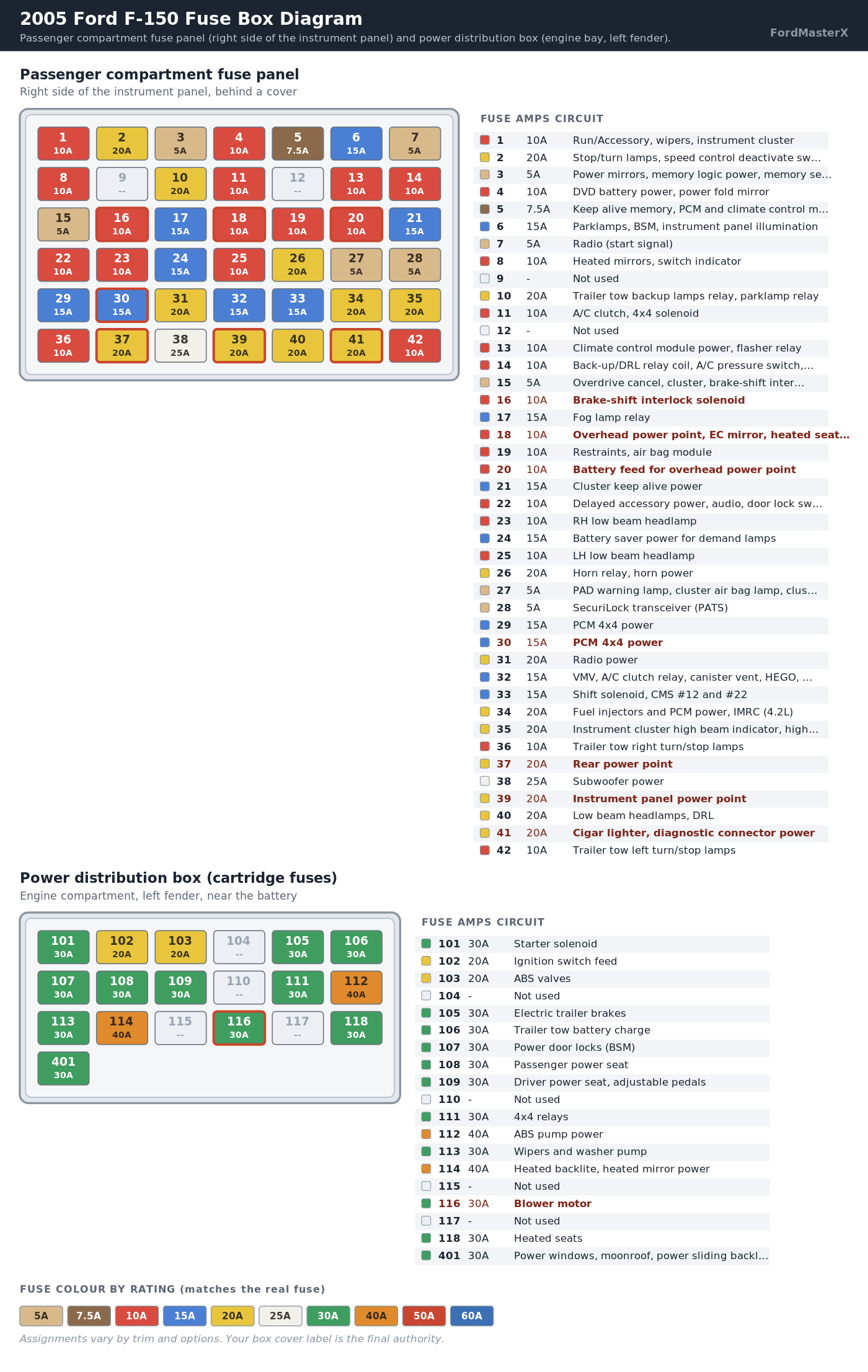
2005 F-150 passenger compartment fuse chart
Right side of the instrument panel, behind the cover. All mini fuses.
| Fuse | Amps | Circuit protected |
|---|---|---|
| 1 | 10A | Run/Accessory: wipers, instrument cluster |
| 2 | 20A | Stop/turn lamps, speed control deactivate switch |
| 3 | 5A | Power mirrors, memory logic power, memory seats and pedals |
| 4 | 10A | DVD battery power, power fold mirror |
| 5 | 7.5A | Keep alive memory for PCM and climate control module |
| 6 | 15A | Parklamps, Body Security Module, instrument panel illumination |
| 7 | 5A | Radio (start signal) |
| 8 | 10A | Heated mirrors, switch indicator |
| 9 | – | Not used |
| 10 | 20A | Trailer tow back-up lamps relay, trailer tow parklamp relay |
| 11 | 10A | A/C clutch, 4×4 solenoid |
| 12 | – | Not used |
| 13 | 10A | Climate control module power, flasher relay |
| 14 | 10A | Back-up lamp and DRL relay coil, A/C pressure switch, redundant speed control switch, reverse park aid, EC mirror (two build variants, see note below) |
| 15 | 5A | Overdrive cancel, cluster, brake-shift interlock |
| 16 | 10A | Brake-shift interlock solenoid |
| 17 | 15A | Fog lamp relay |
| 18 | 10A | Run/Start feed: overhead power point, electrochromatic mirror, heated seats, BSM, compass, RSS |
| 19 | 10A | Restraints (air bag module) |
| 20 | 10A | Battery feed for overhead power point |
| 21 | 15A | Cluster keep alive power |
| 22 | 10A | Delayed accessory power for audio, power door lock switch, moonroof switch illumination |
| 23 | 10A | RH low beam headlamp |
| 24 | 15A | Battery saver power for demand lamps |
| 25 | 10A | LH low beam headlamp |
| 26 | 20A | Horn relay, horn power |
| 27 | 5A | Passenger air bag deactivation lamp, cluster air bag warning lamp, cluster RUN/START power |
| 28 | 5A | SecuriLock transceiver (PATS) |
| 29 | 15A | PCM 4×4 power |
| 30 | 15A | PCM 4×4 power |
| 31 | 20A | Radio power |
| 32 | 15A | Vapor Management Valve, A/C clutch relay, canister vent, HEGO sensors, MAF sensor, VCT |
| 33 | 15A | Shift solenoid, CMS #12 and #22 |
| 34 | 20A | Fuel injectors and PCM power, Intake Manifold Runner Control (4.2L) |
| 35 | 20A | Instrument cluster high beam indicator, high beam headlamps |
| 36 | 10A | Trailer tow right turn/stop lamps |
| 37 | 20A | Rear power point |
| 38 | 25A | Subwoofer power |
| 39 | 20A | Instrument panel power point |
| 40 | 20A | Low beam headlamps, DRL |
| 41 | 20A | Cigar lighter, diagnostic connector power |
| 42 | 10A | Trailer tow left turn/stop lamps |
Fuse 14 has two documented versions for the same model year. A yellow sticker on the fuse panel back means that circuit also covers ABS and heated PCV (5.4L). Without that sticker, the circuit instead routes ABS and the trailer tow back-up lamps relay coil. Check your own sticker before assuming either version.
2005 F-150 power distribution box (cartridge fuse) chart
Recommended Best Deal Products


Same physical panel as above, right side of the instrument panel. These are the flat cartridge fuses, rated higher than the mini fuses.
| Fuse | Amps | Circuit protected |
|---|---|---|
| 101 | 30A | Starter solenoid |
| 102 | 20A | Ignition switch feed |
| 103 | 20A | ABS valves |
| 104 | – | Not used |
| 105 | 30A | Electric trailer brakes |
| 106 | 30A | Trailer tow battery charge |
| 107 | 30A | Power door locks (BSM) |
| 108 | 30A | Passenger power seat |
| 109 | 30A | Driver power seat, adjustable pedals |
| 110 | – | Not used |
| 111 | 30A | 4×4 relays |
| 112 | 40A | ABS pump power |
| 113 | 30A | Wipers and washer pump |
| 114 | 40A | Heated backlite, heated mirror power |
| 115 | – | Not used |
| 116 | 30A | Blower motor |
| 117 | – | Not used |
| 118 | 30A | Heated seats |
| 401 | 30A circuit breaker | Power windows, moonroof, power sliding backlite |
Relays in this same panel:
- R01: starter solenoid
- R02: accessory delay
- R03: high beam headlamps
- R04: heated backlite
- R05: trailer tow battery charge
- R06: blower motor
- R201: trailer tow park lamps
- R202: fog lamps
- R203: PCM
Auxiliary relay box, engine compartment
Left fender, near the battery. Two configurations exist, depending on whether your truck has daytime running lamps or 4×4.
| Position | Rating | Description |
|---|---|---|
| F03 | 5A | Clockspring illumination |
| R01 | Full ISO relay | 4×4, counter-clockwise |
| R02 | Full ISO relay | 4×4, clockwise |
| R03 | V6 ISO relay | Daytime running lamps, high beam disable |
| R201 | Relay | Daytime running lamps |
| R202 | Relay | A/C clutch |
| D01 | Diode | A/C clutch |
Trucks without the DRL or 4×4 options carry a simpler version of this box with fewer active positions. That is normal and not a sign of a missing part.
Why does a 2004 F-150 fuse chart not fully match your 2005?
Recommended Best Deal Products


The 2004 and 2005 F-150 share the same generation and the same cigar lighter fuse, 41. A reader who assumes the rest carries over misses five real changes Ford made between the two years.

Audible — Listen Free for 30 Days
One free credit a month and thousands of titles included.
Listen Free for 30 Days As an Amazon Associate I earn from qualifying purchases.| Fuse | 2004 F-150 | 2005 F-150 |
|---|---|---|
| 16 | 10A, ABS module (Run/Start power) | 10A, brake-shift interlock solenoid |
| 18 | 10A, no overhead power point circuit named | 10A, adds overhead power point to the same circuit |
| 20 | 15A, duplicate PCM 4×4 power | 10A, battery feed for overhead power point |
| 30 | Not used | 15A, PCM 4×4 power |
| 14 | One description, no build variant noted | Two documented build variants, see the note above |
The overhead console power point is the clearest marker. A 2004 chart has no fuse position dedicated to it. Starting in 2005, fuses 18 and 20 both name it directly. Ford wired or documented that outlet differently this model year.
The other direction matters too. A 2006 chart looks nearly identical to 2005 for the positions above. Two different circuits move between 2005 and 2006 instead.
Fuse 3 drops from 5A to 7.5A. Fuel injector control shifts off fuse 34 onto a newly active fuse 9. Our 2006 Ford F-150 fuse box diagram treats that model year on its own terms, not as a 2005 copy.
A “2004-2008” fuse chart is quietly a 2008 chart. Here is the proof.
Several sites publish one combined table and label it 2004 to 2008. Checked against fuse-box.info’s own year-split page, that combined table is not an average of five years. It is the 2008 model year alone, relabeled.
| Fuse | Combined “2004-2008” chart says | Your actual 2005 truck |
|---|---|---|
| 3 | 7.5A | 5A |
| 9 | 20A, fuel pump relay, fuel injectors | Not used |
| 12 | 5A, PCM relay coil | Not used |
| 39 | Not used | 20A, instrument panel power point |
| 41 | Not used | 20A, cigar lighter, diagnostic connector power |
Every one of those five values matches the 2008 column on fuse-box.info’s own page exactly, model year for model year. The 2008 truck also renumbers the whole panel with an F-prefix, F01, F02 and so on. It moves the cigar lighter to F110. A 2005 truck does none of that.
If a chart calls fuse 41 unused and points you to F110, it is showing a 2008 diagram. You have a 2005 truck instead.
Which fuse is the cigar lighter and which fuses are the power points?
The cigar lighter and diagnostic connector share fuse 41, rated 20A. A blown fuse 41 can knock out a scan tool along with the lighter. That matters if you are about to plug one in to read codes.
Two other power points live on separate fuses. The rear power point is fuse 37, 20A. The instrument panel power point is fuse 39, 20A, a second dash-area outlet distinct from the cigar lighter.
If your truck has an overhead console outlet, it draws from two fuses working together. Fuse 18 (10A) supplies Run/Start feed. Fuse 20 (10A) supplies the battery feed. Both have to be good for that outlet to work.
Why do fuses keep blowing, or do lights flicker for no reason?
On this model year and the 2006 that follows it, the leading cause is not a bad fuse at all. It is water reaching the fuse panel itself.
Audible Premium Plus — Annual Membership
12 audiobook credits up front, plus the full Audible catalogue.
See Annual Plans As an Amazon Associate I earn from qualifying purchases.The panel behind your passenger kick panel is a Smart Junction Box. Common entry points: a deteriorating windshield seal, a clogged cowl or HVAC drain, a failed third brake light gasket. Water inside that box causes scattered symptoms that send people chasing individual fuses instead:
- Flickering or dead interior lighting
- Power windows and door locks acting up
- A horn that fires on its own, or quits completely
- Trailer lights failing
- A battery that drains overnight
Replacing fuse after fuse does not fix water damage inside the box. If you have more than one unrelated symptom at once, check for moisture at the kick panel before buying parts. A failed Smart Junction Box on this generation is a documented replacement part, Ford number 5L3T-14A067-BC. Fix the leak source first, or the replacement fails the same way.
A slow overnight battery drain from this cause is also the reason a healthy-looking replacement battery can still go flat. Chasing the battery without finding the leak just delays the same complaint.
Which fuse controls the blower motor, A/C and heated seats?
| Symptom | Check this |
|---|---|
| Blower does not run at any speed | Fuse 116, 30A, and relay R06 |
| Fan runs but air never gets cold | Fuse 11, 10A, A/C clutch |
| Heated seats dead | Fuse 118, 30A |
| Climate control panel completely dark | Fuse 13, 10A |
The blower motor fuse is a 30A cartridge fuse in the same cab-mounted panel as everything else. It is not a separate engine-bay box.
If the fan runs on one speed but not others, the fuse is fine. The fan speed switch or blower motor resistor is the more likely part. This same failure pattern shows up across the whole F-150 fuse cluster.
Which fuse stops a 2005 F-150 from starting?
- Fuse 28, 5A. SecuriLock transceiver (PATS). The anti-theft system can let the truck crank while blocking fuel or spark.
- Fuse 101, 30A (cartridge). Starter solenoid. No crank at all points here first.
- Fuse 102, 20A (cartridge). Ignition switch feed.
- Fuse 34, 20A. Fuel injectors and PCM power. Cranks normally but will not fire.
No crank points at 101 or 102. Cranks but will not fire points at 34, then 28 if the anti-theft light is behaving oddly.
How do you tell if a fuse is actually blown?
Pull it and look through the plastic window at the metal element. An intact fuse shows an unbroken strip. A blown one shows a visible gap or a window smoked brown or black.
A hairline break can still look intact to the eye. If you are not certain, test continuity with a multimeter set to ohms. Near zero ohms means the fuse is good.
The cartridge positions, 101 through 118, need a puller rather than fingers or pliers. A mixed fuse assortment kit costs less than one dealer fuse. Most kits include a puller sized for both fuse types.
Never guess the replacement rating. Match the number printed on the fuse itself, then confirm it against the label inside your own box cover. Fitting a 30A fuse where a 10A belongs lets the wiring absorb the overload instead of the fuse.
2005 F-150 fuse quick reference
The positions owners look up most, in one place.
| What you want | Fuse | Amps |
|---|---|---|
| Cigar lighter, diagnostic connector | 41 | 20A |
| Rear power point | 37 | 20A |
| Instrument panel power point | 39 | 20A |
| Overhead console power point | 18 and 20 | 10A each |
| Radio | 31 | 20A |
| Blower motor | 116 | 30A |
| A/C clutch | 11 | 10A |
| Horn | 26 | 20A |
| High beam headlamps | 35 | 20A |
| Low beam, right / left | 23 / 25 | 10A each |
| Power windows, moonroof | 401 | 30A breaker |
| Heated seats | 118 | 30A |
| Starter solenoid | 101 | 30A |
| Anti-theft (PATS) | 28 | 5A |
If your truck is a model year earlier, our 2002 Ford F-150 fuse box diagram covers the older, driver-side layout. If it is a model year later, the 2006 Ford F-150 fuse box diagram covers what actually changes. For an electrical fault, not just a blown fuse, two guides help. Our Ford diagnostic tool comparison and best OBD2 scanner for the F-150 both cover what reads live data here.