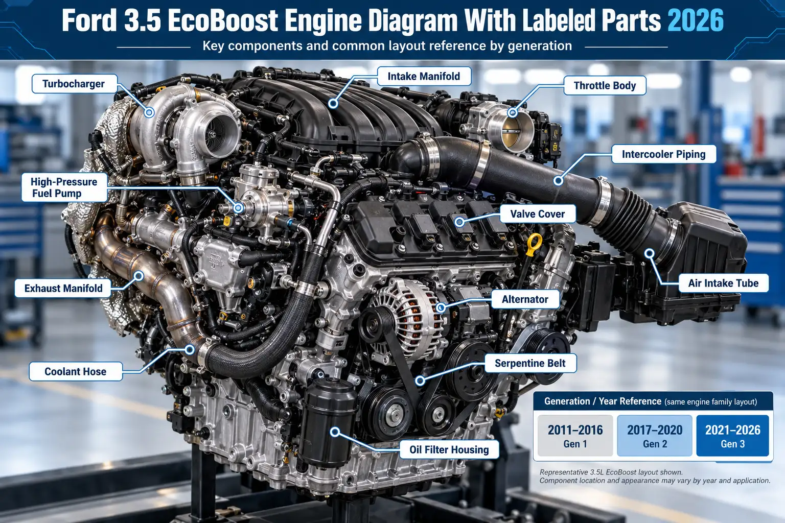
Ford 3.5 EcoBoost Engine Diagram With Labeled Parts by Year 2026

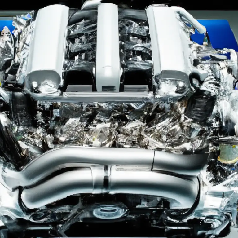
A Ford 3.5 EcoBoost engine diagram helps you identify the twin turbochargers, intake system, fuel pump, timing components, and service points on your F-150. The right diagram depends on the model year: Ford used the first-generation 3.5L EcoBoost in 2011–2016 F-150s and introduced a redesigned second-generation engine for 2017.
This guide covers the standard, longitudinally mounted 3.5L EcoBoost V6 in US-market F-150 trucks through 2026. It separates under-hood service items from internal engine parts so you know what you can see without disassembly and what requires a dedicated service illustration.
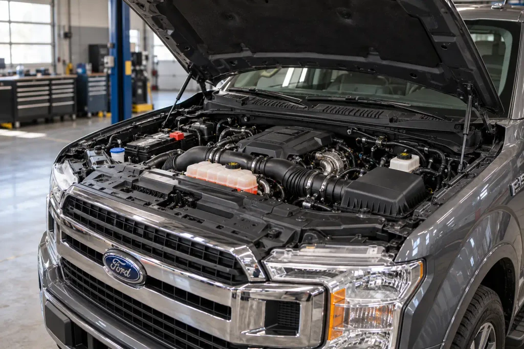
Ford F-150 | 3.5L twin-turbo V6
Which Engine Diagram Fits Your Truck?
Match the year and engine variant before using a component-location drawing.
01 / Select your F-150 model-year group
2011–2016
First generationFuel injection
Direct injection
Diagram to choose
Early 3.5L EcoBoost engine assembly and service-point view.
2017–2020
Second generationFuel injection
Port + direct injection
Diagram to choose
Redesigned 3.5L engine with the correct dual-injection layout.
2021–2026
Later applicationsEngine reference
Standard 3.5L EcoBoost
Diagram to choose
Your exact model-year under-hood and component drawings.
02 / Verify in three checks
03 / Read the view correctly
Engine front faces the radiator. Engine rear faces the firewall. Hidden parts need a separate assembly or exploded view.
Do not interchange diagrams: PowerBoost Hybrid, Raptor High Output, and transverse 3.5L applications require their own references.
Identification guide only. Confirm exact part positions, connectors, and repair steps in Ford service information for your vehicle.
Which Ford 3.5 EcoBoost Diagram Matches Your Year
Recommended Best Deal Products

Start with your F-150’s model year and engine identification. A 2013 engine diagram is not a reliable parts-location reference for a 2019 truck, even though both engines carry the 3.5L EcoBoost name.
| F-150 model years | Engine reference | Diagram to use |
|---|---|---|
| 2011–2016 | First-generation 3.5L EcoBoost | Early engine and direct-injection layout |
| 2017–2020 | Second-generation 3.5L EcoBoost | Redesigned engine with dual-injection components |
| 2021–2026 | Later standard 3.5L EcoBoost applications | Year-specific under-hood and service illustrations |
The last row is a diagram lookup group, not a third engine generation. Equipment, plumbing, and service-item layouts can change without a new engine-generation designation.
Confirm the engine through your vehicle information, the under-hood emissions label, and the corresponding Ford owner’s or service manual. Do not substitute diagrams for the 3.5L naturally aspirated V6, PowerBoost Hybrid, or Raptor High Output engine merely because the displacement matches.
What the Ford 3.5 EcoBoost Engine Diagram Shows
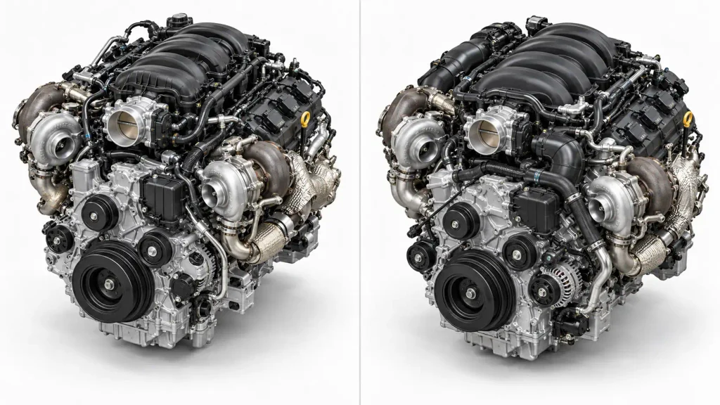
A useful engine diagram identifies both visible service items and mechanical components that sit behind covers or lower in the engine bay. Use these landmarks when reading an engine illustration.
| Component | Where to look | What it does |
|---|---|---|
| Intake manifold | Upper engine, between the cylinder banks | Distributes air to six cylinders |
| Valve covers | Upper outside of each cylinder bank | Enclose the valve-train area |
| Two turbochargers | Low on opposite sides, close to the exhaust outlets | Use exhaust energy to compress intake air |
| Charge-air cooler | In the front-end cooling and air path | Cools compressed intake air |
| High-pressure fuel pump | Mounted on the engine; position varies by generation | Supplies pressurized fuel for direct injection |
| Throttle body | At the intake-manifold inlet | Controls incoming airflow |
| Timing chains and cam phasers | Behind the engine’s front timing cover | Drive and adjust camshaft timing |
| Pressure and camshaft sensors | Intake piping, manifold, and cylinder-head areas | Report operating conditions to the engine computer |
Diagram orientation matters: The front of the engine faces the radiator; the rear faces the firewall. Engine left and right should be interpreted using Ford’s specified viewpoint, not an unlabeled picture found online. An under-hood view cannot show the timing chains or every turbo connection.
For cylinder-bank numbering and ignition sequence, use the separate 3.5 EcoBoost firing order and cylinder layout diagram. Those details have a dedicated reference and do not need to be repeated here.
Where 2011 to 2016 EcoBoost Components Sit
Recommended Best Deal Products


The 2011–2016 F-150 uses the original twin-turbo 3.5L EcoBoost with gasoline direct injection. Its fuel-system diagram shows direct injectors and a mechanically driven high-pressure pump, rather than the second-generation combination of port and direct injectors.
On an assembled engine, the intake manifold and valve covers occupy the upper area. Each turbocharger sits lower along its respective exhaust side. Intake tubing connects the air supply to the compressors, while charge pipes carry boosted air forward through the charge-air cooler and back toward the throttle body.
For routine service, Ford’s 2016 F-150 under-hood overview identifies eight items: washer reservoir, battery, oil filler cap, oil dipstick, brake-fluid reservoir, coolant reservoir, air-filter assembly, and power distribution box.
That owner’s-manual illustration is a maintenance map. It is not an exploded engine assembly or a guide to hidden timing components. For the latter, use service information matching the actual model year.
How the 2017 to 2020 EcoBoost Layout Changed
Ford introduced the second-generation 3.5L EcoBoost in the 2017 F-150. The most important diagram difference is its combined port and direct fuel injection, along with revised turbocharger and valve-train hardware.
The 2017 design has two fuel injectors per cylinder: one at the intake port and one injecting directly into the combustion chamber. Across the V6, that means six port injectors and six direct injectors. A fuel-system drawing from a 2015 truck will not account for the second set.
Ford also introduced revised twin turbos with electrically controlled wastegates and a redesigned valve train. These changes are described in Ford’s 2017 EcoBoost technical announcement.
Do not identify the generation by a plastic engine cover alone. Verify the model year, engine application, and the correct parts illustration before ordering injectors, turbo components, or timing parts.
Which 2021 to 2026 F-150 Components Differ
Recommended Best Deal Products


For a 2021–2026 standard 3.5L EcoBoost F-150, use an under-hood reference from the truck’s own year. A diagram from a later F-150 may show familiar service items, but that does not prove every connector, bracket, or hose has the same location.
Ford’s 2026 F-150 3.5L EcoBoost under-hood diagram provides this maintenance legend:
| Ford callout | Under-hood item |
|---|---|
| A | Engine compartment fuse box |
| B | Battery |
| C | Engine oil filler cap |
| D | Engine oil dipstick |
| E | Brake-fluid reservoir |
| F | Air filter |
| G | Engine coolant reservoir |
| H | Windshield washer-fluid reservoir |
These letters describe that particular Ford illustration. They must not be applied to the 2016 diagram, which uses different callout letters.
The standard EcoBoost, PowerBoost Hybrid, and Raptor High Output are distinct engine applications. Check the powertrain listed for your truck before using a diagram for anything beyond general service-point recognition.
Where the 3.5 EcoBoost Turbos and Charge Pipes Sit
The 3.5L EcoBoost uses two turbochargers, one associated with each cylinder bank’s exhaust flow. On a longitudinal F-150 installation, the assemblies sit low along the engine sides and can be partly concealed by heat shielding, ducting, and surrounding hardware.
The intake-air route is easier to understand as a system diagram than by following a single hose in a photograph:
Air-filter assembly → turbo compressor inlets → compressor outlets → charge-air cooler → throttle body → intake manifold → cylinders
That sequence describes the boosted air path, not the exact physical route of each pipe. The exhaust side drives the turbo turbines and then routes exhaust downstream. Turbo oil-feed, oil-return, and coolant connections belong to separate circuits and should never be confused with charge-air hoses.
The actual pipe shapes, clamps, and wastegate actuator arrangement depend on the engine generation and application. If you need to identify the housings on your truck, the dedicated guide to where both 3.5 EcoBoost turbochargers are located goes beyond this system overview.
How the 3.5 EcoBoost Fuel System Is Arranged
The fuel-system diagram changes substantially at the 2017 redesign. Both generations use a high-pressure system for direct injection, but the second-generation F-150 engine adds a separate port-injection path.
| Fuel-system feature | 2011–2016 F-150 | 2017–2020 F-150 |
|---|---|---|
| Direct fuel injection | Yes | Yes |
| Port fuel injection | No | Yes |
| Injector arrangement | One direct injector per cylinder | One direct plus one port injector per cylinder |
| High-pressure fuel pump | Supplies direct-injection system | Supplies direct-injection system |
The in-tank fuel supply and the high-pressure pump perform different jobs. The low-pressure side feeds fuel forward; the engine-driven high-pressure pump provides the pressure needed by the direct-injection rail. The port-injection circuit on the redesigned engine must be identified separately in the matching fuel-system drawing.
Do not mistake a fuel-pressure sensor, a pump control connector, or a metal fuel line for a serviceable fuel-line disconnect. Direct-injection components can retain dangerous pressure after the engine is shut off. Use Ford’s depressurization procedure before disconnecting fuel-system hardware.
Where the 3.5 EcoBoost Timing Chains and Phasers Sit
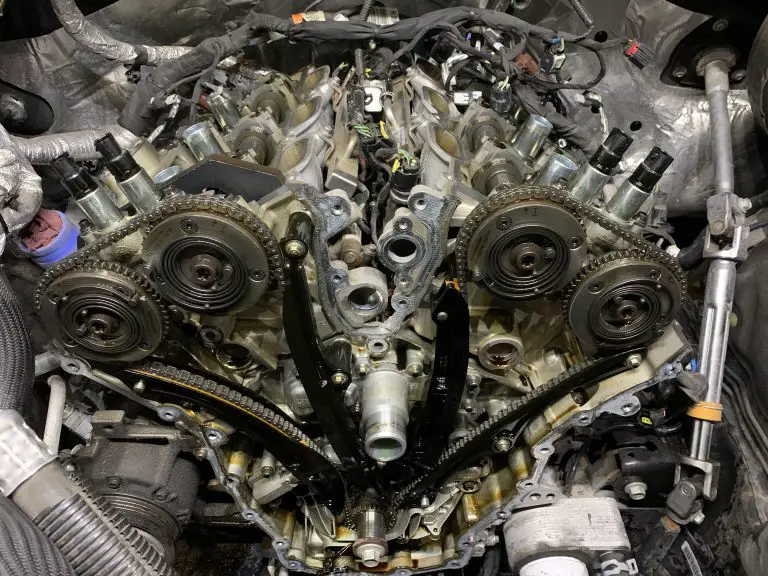
The timing chains and cam phasers are behind the front timing cover, so an ordinary photograph looking down into the engine bay cannot show their actual positions. A timing-system exploded view identifies the crankshaft drive, camshaft timing sprockets, guides, tensioners, and variable cam timing components.
The cam phasers attach to the camshaft drive and change camshaft timing under engine control. Variable camshaft timing solenoids regulate the oil control used to operate that system; they are not the same parts as the phasers behind the cover.
Supplier documentation for the second-generation engine identifies its VCT phasers and engine timing hardware as distinct systems within the engine assembly.
An exploded parts view helps identify components, but it does not establish the timing alignment or bolt-tightening sequence. For the actual work, consult the 3.5 EcoBoost cam phaser replacement guide alongside the correct Ford service procedure.
How to Find 3.5 EcoBoost MAP and VCT Sensors
Sensor identification starts by separating what the sensor measures from where it is mounted. A connector appearing in roughly the same area on two generations may serve a different circuit or use a different Ford component name.
Pressure Sensors on the Intake System
A manifold absolute pressure sensor reports pressure in the intake manifold. Charge-air pressure and temperature sensing also occurs along the boosted intake tract, but Ford’s names and sensor combinations can vary by year. Trace the air path first, then match the electrical connector to a model-specific component illustration.
For a closer component lookup, use the dedicated 3.5 EcoBoost MAP sensor location guide. It is more appropriate than guessing a sensor from an unmarked engine photograph.
Camshaft Sensors and VCT Controls
Camshaft position sensors report camshaft position to the engine computer. Variable cam timing solenoids are actuators that control oil flow for cam timing; a solenoid is not a camshaft position sensor.
Look for these components in the cylinder-head and valve-cover service illustrations rather than relying on a general under-hood drawing. The exact connector count, side, and access method must be verified for the truck’s engine application.
How to Match Your F-150 to the Correct Diagram
Use this four-step check before treating an online illustration as a parts-location reference.
- Confirm the vehicle. Record the F-150 model year and engine variant from the vehicle documentation, emissions label, or VIN-based service lookup. The badge alone is not enough.
- Choose the matching engine illustration. Identify the 2011–2016 first generation, 2017–2020 second generation, or the later model-year-specific standard EcoBoost reference. Do not swap in PowerBoost or Raptor drawings.
- Orient the picture. Find the radiator side, firewall side, upper intake area, and the two cylinder banks. Then compare the visible airbox, filler cap, reservoirs, and other landmarks with the truck.
- Verify the exact part. Match the Ford service description, connector, and assembly location before removing anything. For fuel, timing, or turbo work, use the applicable workshop procedure instead of a general identification chart.
If the drawing does not match the components you can see, stop there. The mismatch is a reason to find another reference, not to force the parts to fit the picture.
How to Check Ford 3.5 EcoBoost Component Locations
The correct Ford 3.5 EcoBoost engine diagram should answer two questions: which engine application is shown, and whether the part is visible from the stated viewpoint. For 2011–2016 trucks, start with first-generation direct-injection references. For 2017–2020 models, account for the redesigned dual-injection system and turbo hardware. For newer F-150s, use the under-hood diagram for the exact model year.
Use the component table to recognize the intake, twin turbos, fuel system, and hidden timing assembly. Then move to a component-specific service drawing when a repair requires a precise connector, fitting, or fastener location. Confirm the year and variant before ordering a part or beginning disassembly.
Ford 3.5 EcoBoost Engine Diagram FAQs
Where Can I Find a Labeled Ford 3.5 EcoBoost Engine Diagram?
Ford’s F-150 owner’s manuals include labeled under-hood illustrations showing maintenance items such as the oil filler, air filter, and coolant reservoir. For turbos, fuel injectors, and timing parts, look for a matching year-specific Ford workshop or OEM assembly diagram rather than an ordinary maintenance illustration.
Are the 2013 and 2018 3.5 EcoBoost Engine Diagrams the Same?
No. A 2013 F-150 uses the first-generation direct-injected 3.5L EcoBoost, while the 2018 F-150 uses the redesigned second-generation engine with port and direct injection. General landmarks may be similar, but detailed fuel-system, turbo, sensor, and timing illustrations should match the specific engine.
Where Are the Turbos on a 3.5 EcoBoost F-150?
The two turbochargers sit low along opposite sides of the longitudinal engine near the exhaust outlets. They are not normally both easy to see from directly above because other engine-bay components obscure them. Use an application-specific side view when identifying either turbo or its lines.
Does the 3.5 EcoBoost Have a Timing Belt or Timing Chain?
The F-150 3.5L EcoBoost uses timing chains, not a rubber timing belt, to drive its camshafts. Chains, guides, tensioners, and cam phasers are housed behind the front timing cover. Correct alignment and service requirements differ by application, so the engine diagram alone is not a repair procedure.
Can I Use an F-150 3.5 EcoBoost Diagram for an Explorer?
Not as a component-location reference. Many earlier 3.5L EcoBoost Explorer applications mounted the engine transversely, while the F-150 mounts it longitudinally. Even when the engine family is related, the visible bank orientation, turbo locations, hoses, and surrounding components differ. Use the Explorer’s own model-year-specific service diagram.