Ford Bronco Aux Switch Wiring Diagram: Wiring & Maintenance 2026

The Ford Bronco auxiliary switch bank utilizes a bundle of blunt-cut wires located in the engine compartment near the passenger-side cowl. These switches connect to a dedicated fuse box. Pins are pre-wired to specific relays; the hot wire is color-coded by switch, while the common ground wire is typically black.
📌 Key Takeaways
- Aux switches 1-4 are rated for 15 amps, while switches 5-6 handle up to 30 amps.
- The blunt-cut wire bundle is located behind the glove box or in the engine bay depending on the model year.
- Always ensure your accessory ground wire is connected to a dedicated chassis grounding point, not a floating common ground.
- Mixing up the hot wire and the signal wire can cause immediate fuse failure or switch malfunction.
- Consult an ASE-certified technician if you are integrating aftermarket high-draw LED light bars to avoid factory harness damage.
The Ford Bronco’s auxiliary switch system is a sophisticated factory-integrated solution designed to streamline the power distribution for high-draw aftermarket accessories. Whether you are installing heavy-duty LED light bars, on-board air compressors, or specialized off-road recovery gear, understanding the bronco aux switch wiring diagram is essential to maintaining vehicle integrity. By utilizing the overhead switch bank and the dedicated engine bay auxiliary power distribution box (PDB), you ensure your equipment operates within the manufacturer’s established voltage thresholds while preventing electrical feedback into the sensitive CAN-bus network. This guide details the pin assignments, factory wire colors, and critical safety protocols required for professional-grade aftermarket accessory integration.
Decoding the Bronco Aux Switch Wiring Diagram and PDB


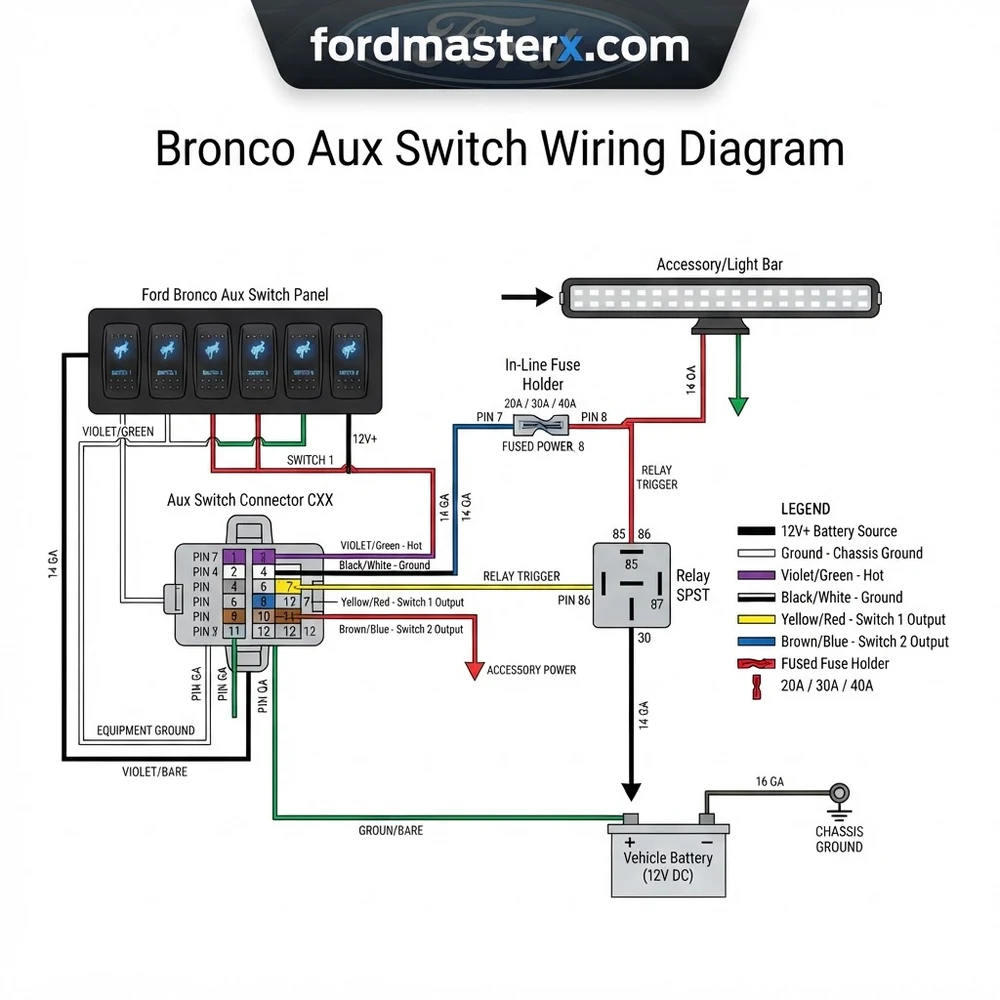
The Bronco auxiliary electrical architecture is divided into two primary zones: the overhead console switch bank and the secondary power distribution box located in the engine compartment. The overhead switches function as low-current triggers for the relays housed within the engine bay PDB. When you toggle a switch, the control circuit activates the respective relay, which then closes the high-current path from the battery to the designated accessory circuit.
The Overhead Switch Bank Mechanics
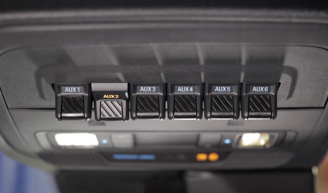
Each of the six auxiliary switches on the overhead console is rated for specific amperage, ranging from 10A to 30A depending on the switch position and the associated fuse block location. The logic signal from these switches travels through the vehicle’s main wiring harness to the PDB, where it engages the factory-installed relays. It is imperative to distinguish between the control-side wiring, which utilizes low-gauge signal wire, and the load-side wiring, which uses higher-gauge wire to manage current flow.
Power Distribution and Relay Triggering
The PDB contains the relay bank that serves as the bridge between your accessory and the battery. When interpreting the bronco aux switch wiring diagram, observe that the relay trigger is powered by the ignition-run circuit (or battery constant, depending on the specific model year). The load side of the relay connects directly to the bundle of pass-through wires located near the cowl on the passenger side of the engine bay. These wires are factory-sealed to prevent moisture ingress. Failing to account for the specific relay current rating can result in thermal degradation of the fuse block or, in extreme cases, a total loss of the auxiliary electrical segment.
Bronco Aux Switch Wiring Diagram: Wire Color Reference Table


Correct identification of the factory pigtail wires is the most critical step in preventing short circuits. These wires are color-coded based on the specific switch they control. Use the following table to map the auxiliary circuit to the engine bay pigtail. Ensure you verify the gauge size and color code against your specific vehicle build sheet, as manufacturer mid-year revisions may occasionally alter the specific pigtail bundle location.
| Switch | Wire Color Code | Max Current | Recommended Gauge |
|---|---|---|---|
| AUX 1 | Yellow/Orange | 30A | 12 AWG |
| AUX 2 | Yellow/Violet | 15A | 14 AWG |
| AUX 3 | Yellow/Blue | 15A | 14 AWG |
| AUX 4 | Yellow/Green | 10A | 16 AWG |
| AUX 5 | Yellow/Brown | 10A | 16 AWG |
| AUX 6 | Yellow/White | 10A | 16 AWG |
Always use heat-shrink butt connectors or automotive-grade soldering techniques when extending these wires. The pass-through wires are located near the firewall on the passenger side, encased in heat-shrink tubing to protect against engine bay heat and debris.
How to Read the Bronco Aux Switch Wiring Diagram Step by Step



Successful integration requires a methodical approach to circuit completion. Before cutting any factory wiring, ensure you have disconnected the negative battery terminal to prevent accidental shorts.
Phase 1: Locating the Pass-Through Bundle
The auxiliary pass-through wires are located inside the engine bay near the passenger side firewall. Look for the taped-off bundle of wires protruding from the main harness conduit. These are your load-side wires. Verify the colors against the provided reference table above to confirm which circuit corresponds to your desired overhead switch.
Phase 2: Proper Termination and Grounding
Once you have identified the hot wire for your accessory, you must establish a reliable ground. Do not rely on the factory harness for grounding. Instead, use one of the chassis-mounted grounding studs located near the PDB. Use a terminal block if you are installing multiple accessories to prevent crowding the factory grounding point, which could lead to increased resistance and heat.
Phase 3: Connection Procedures
Connect your accessory positive lead to the identified color-coded wire from the pass-through bundle. Ensure the wire gauge used on your accessory matches or exceeds the gauge provided by the factory circuit to prevent voltage drop. Secure the connection using dual-wall, adhesive-lined heat shrink. This ensures the bronco aux switch wiring diagram remains sealed against moisture, a critical requirement for off-road environments.
Phase 4: Testing Circuit Integrity
After finalizing connections, re-connect the negative battery terminal. Use a digital multimeter to measure voltage at the accessory connection point while the engine is running and the switch is engaged. A healthy circuit should show a voltage reading within 0.2V of the battery voltage. Any significant drop indicates a high-resistance connection that needs immediate correction.
Common Bronco Aux Switch Wiring Diagram Problems and Fixes
Electrical gremlins in the Bronco’s auxiliary system are rarely caused by the factory wiring itself; they are almost exclusively the result of improper load calculations or inadequate grounding. Understanding how to diagnose these issues will save your PDB from premature failure.
Resolving Blown Fuses and Overload Situations
If you find that an auxiliary switch is not powering your accessory, the first step is to check the PDB fuse. The bronco aux switch wiring diagram illustrates that each switch has a specific fuse location in the power distribution center. If you consistently blow fuses, your accessory is exceeding the circuit’s amperage limit. For high-draw items like winches or dual-compressor setups, use the aux switch only as a trigger for a larger, auxiliary external relay or a dedicated contactor.
Troubleshooting Flickering or Intermittent Power
Intermittent power is usually a symptom of a poor ground wire connection. Because the Bronco uses a lightweight aluminum chassis in various segments, ensure that your ground ring terminal is bolted to a clean, unpainted steel chassis point. Avoid using painted surfaces, as the resistance will build heat and trigger a thermal protection shut-off within the switch logic.
Never attempt to “jump” a higher amperage load onto a lower-rated fuse circuit. This creates an immediate fire hazard and can melt the wiring harness, which is not covered under the manufacturer’s powertrain or electrical warranty.
Bronco Aux Switch Wiring Diagram Questions Answered
Can I change the switch configuration to be “Always On”?
By default, the bronco aux switch wiring diagram is configured for ignition-switched power. Modifying this requires rewiring the relay control side within the PDB to a constant 12V source. This is not recommended, as it bypasses the vehicle’s battery protection logic and can lead to a dead battery if an accessory is left on while the vehicle is parked.
Why does my accessory stay on after I turn off the ignition?
If your accessory remains powered, it is likely that your relay is stuck in the closed position or you have inadvertently spliced into a constant-hot source instead of the ignition-switched signal wire. Re-verify your pin assignment against the factory harness map to ensure you are tapped into the ignition-controlled circuit.
What is the largest accessory I can run on AUX 1?
AUX 1 is rated for 30A. However, you should calculate your accessory’s peak draw—not just its continuous draw—before connecting it. If your device has a high inrush current, such as an air compressor motor, ensure the total peak current does not exceed 30A for more than a few milliseconds, or the PDB circuit protection will trip.
Do I need to add a secondary fuse if the circuit is already fused?
While the PDB provides circuit protection, it is professional practice to include an inline fuse near the device itself if the accessory manufacturer requires it. This protects the accessory-side wiring from shorts that might occur between the PDB and the device, ensuring that the bronco aux switch wiring diagram remains a secondary layer of safety rather than your only line of defense.
When routing wires through the firewall, always utilize existing factory grommets. Drilling new holes compromises the weather-tight seal of the cabin, which can lead to moisture damage in the floorboard wiring harnesses.
Step-by-Step Guide to Understanding the Bronco Aux Switch Wiring Diagram
Identify – Locate the blunt-cut accessory wire bundle inside the engine bay or cabin header based on your vehicle trim.
Locate – Use a multimeter to confirm the hot wire associated with the specific switch number you intend to use.
Reference – Consult the wire color code chart to match your accessory power lead to the correct factory output.
Connect/Route – Secure your accessory ground wire to a clean metal chassis point and crimp the hot lead using waterproof connectors.
Verify – Toggle the switch to the ‘on’ position and confirm power delivery at the accessory using a test light.
Troubleshoot – If the switch fails to illuminate or power the device, check the corresponding relay and fuse in the Power Distribution Box.