Ford F250 4×4 Front Axle Parts Diagram: 2026 Component Breakdown

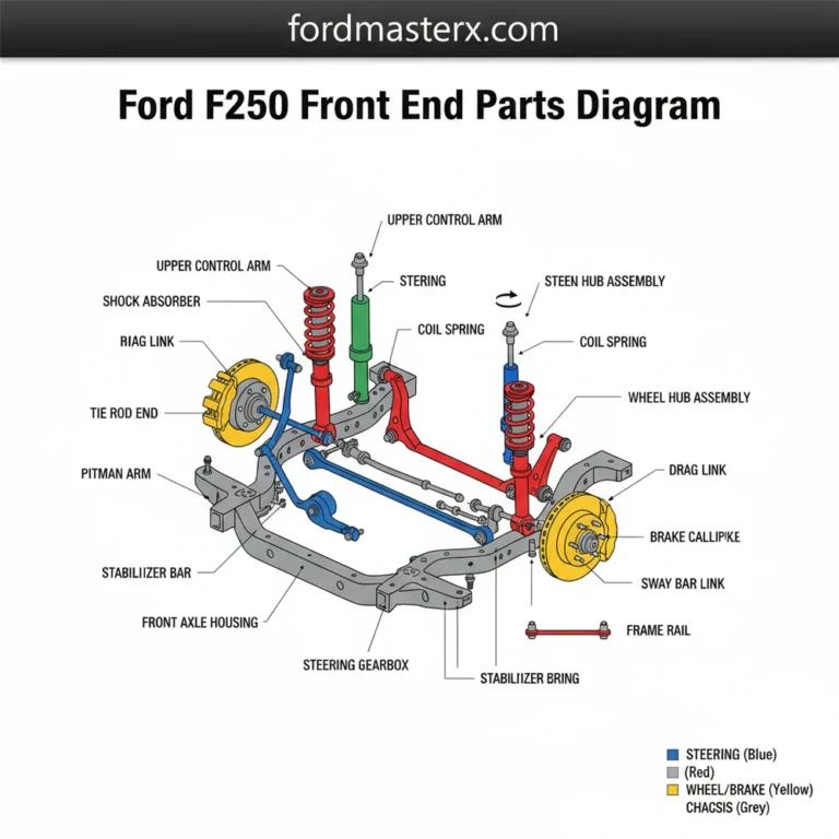
The front axle system on a Ford F250 integrates the differential assembly, inner/outer axle shafts, unit bearings, and vacuum-actuated locking hubs. Refer to the diagram to locate the driver-side vacuum seal and passenger-side splined shaft connection. Critical torque specifications for unit bearing bolts are 120 lb-ft, ensuring proper structural integrity.
📌 Key Takeaways
- Unit bearing mounting bolts require a precise torque specification of 120 lb-ft to prevent hub play.
- The CAD (Central Axle Disconnect) system or manual hub lock is the primary identification point for 4×4 engagement issues.
- Always replace axle seals when disassembling the shaft to prevent differential fluid leaks.
- The most common failure point is the needle bearing inside the hub, leading to grinding noises at speed.
- Seek professional help if the differential housing shows internal metal debris or damaged ring gear teeth.
Mastering the maintenance of Ford Super Duty vehicles requires a profound understanding of the solid front axle assembly. The 4×4 front Ford F250 front axle parts diagram serves as the definitive roadmap for technicians tasked with managing the Dana 60 or Sterling-based configurations common in these heavy-duty platforms. Whether you are addressing steering oscillations, driveline vibrations, or engaging the vacuum-actuated locking hubs, referencing the correct schematic is paramount for structural integrity. This guide dissects the complex layout of the F-250 drivetrain, providing the technical depth necessary for precise component identification, diagnostic verification, and adherence to OEM service specifications.

Prime for Young Adults — 6 Months Free
Students and 18–24s get six months of Prime free, then half price.
Start 6 Months Free As an Amazon Associate I earn from qualifying purchases.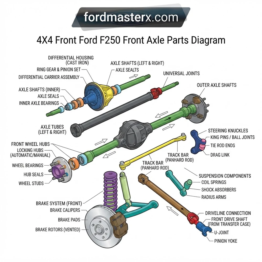
4×4 Front Ford F250 Front Axle Parts Diagram: Component Overview
Recommended Best Deal Products


The structural configuration of the Ford F-250 front drivetrain relies on a solid axle design that prioritizes durability under load. Understanding the specific placement of these internal components is critical, as the interaction between the carrier, the axle shafts, and the outer hub assemblies dictates the vehicle’s off-road and towing performance. Below is a detailed breakdown of the primary mechanical elements found within the system.
| Component | Primary Function | Technical Note |
|---|---|---|
| Axle Housing | Structural load-bearing member | Verify alignment after heavy impact |
| Differential Carrier | Gear reduction and power distribution | Requires precise backlash settings |
| Inner Axle Shaft | Transmits torque to the knuckle | Check splines for wear patterns |
| U-Joint Assembly | Facilitates steering angle articulation | Non-serviceable sealed bearings |
The axle housing acts as the foundation of the 4×4 front Ford F250 front axle parts diagram. It encapsulates the ring and pinion set, which must maintain a specific contact pattern to prevent premature gear fatigue. The differential carrier utilizes a spider gear configuration to allow for speed variation between the wheels during turning maneuvers while ensuring constant power delivery when locked. Moving outboard, the inner axle shafts pass through the carrier and connect to the outer stub shafts via high-strength U-joints. These U-joints are the most frequent point of failure in the configuration; they are subjected to extreme stress during tight-radius turns under load. The housing itself must remain free of weld fractures, particularly around the “C” ends, where the steering knuckles attach. Any structural deflection in the tube can lead to severe misalignment, manifesting as uneven tire wear or erratic handling at highway speeds.
On post-2005 Ford F-250 models, the transition to coil-spring front suspensions changed the geometry of the radius arm mounts. Always confirm your specific manufacturing date against the parts diagram, as axle tube diameters and caster bushings vary significantly across production years.
How to Inspect Your 4×4 Front Ford F250 Front Axle Parts Diagram
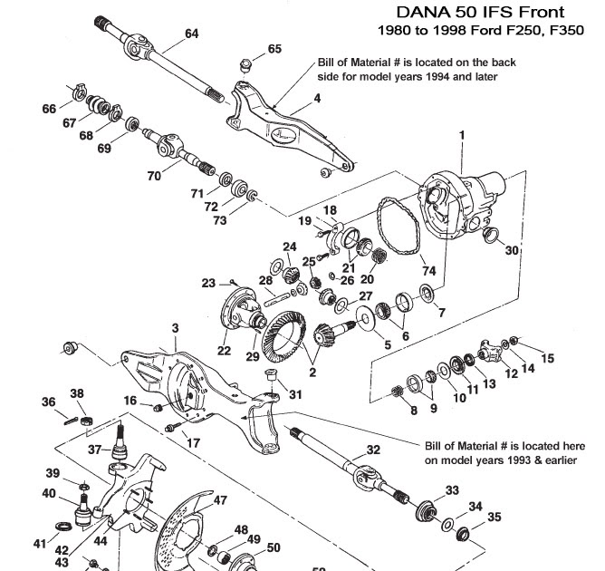
A systematic inspection of the front-end assembly prevents catastrophic mid-journey failures. By using the 4×4 front Ford F250 front axle parts diagram as a reference, you can identify wear points before they compromise vehicle control. Follow these diagnostic steps to verify system integrity.
1. Ball Joint Integrity Check: With the vehicle supported on jack stands and the tires removed, use a pry bar under the tire to detect vertical movement in the steering knuckle. Excessive play, exceeding the manufacturer’s limit of 0.060 inches, indicates worn upper or lower ball joints. Cross-reference the diagram to locate the grease zerks, if applicable, noting that many factory joints are sealed for life.
2. U-Joint Articulation: Rotate the axle shaft manually while the hubs are in the “Free” position. Feel for notchiness or audible clicks. If the U-joint is frozen or exhibits play, it will likely induce significant vibration through the steering column when the 4×4 system is engaged. Inspect the rubber seals surrounding the cross-journals for dry rot or missing grease.
3. Hub Actuator Vacuum Testing: Utilize a vacuum pump to test the pulse vacuum hub lock (PVH) system. Connect the pump to the vacuum port on the knuckle assembly. If the system fails to maintain a vacuum, the internal seal is likely compromised, preventing the hubs from engaging in 4×4. Consult the blueprint to verify the routing of the vacuum lines, as they are susceptible to heat soak and puncture.
4. Pinion Seal Leak Detection: Inspect the area around the front driveshaft flange. A wet, greasy residue indicates a failed pinion seal. If ignored, the drop in differential oil levels will lead to catastrophic gear failure. Before replacing, inspect the pinion yoke for deep grooving that might prevent the new seal from seating properly.
Common 4×4 Front Ford F250 Front Axle Parts Diagram Repair Issues
Recommended Best Deal Products


Mechanical failures in the Super Duty front axle are often predictable but require specialized tools to rectify. Referencing the 4×4 front Ford F250 front axle parts diagram during the teardown process helps prevent common mistakes, such as the misorientation of hub internal components or incorrect torquing of the unit bearing bolts.

Audible — Listen Free for 30 Days
One free credit a month and thousands of titles included.
Listen Free for 30 Days As an Amazon Associate I earn from qualifying purchases.- Locking Hub Failure: Often caused by excessive grease clogging the locking mechanism, which prevents the shift collar from sliding into position. Clean the assembly with non-chlorinated brake cleaner rather than forcing the dial, which can shear the plastic retention tabs.
- Vacuum Hub Actuator Leaks: The internal “O-ring” style seal in the hub assembly is prone to degradation. If the front hubs remain locked even when the dashboard switch is in “2WD,” suspect a stuck vacuum actuator.
- Axle Shaft Oil Seal Seepage: Located deep within the axle housing, this seal prevents differential fluid from leaking into the axle tube and out toward the hub. Replacing this requires removing the entire axle shaft and utilizing a specialized seal installation tool to seat the seal perpendicular to the tube bore.
- Caster/Camber Misalignment: If the vehicle exhibits a pull or wanders, the issue may lie in the caster bushings at the top of the steering knuckle. Using the blueprint, verify the position of the eccentric sleeve to ensure the caster settings are within the factory range of +3.5 to +4.5 degrees.
Never attempt to service the internal components of the axle without a torque wrench calibrated to factory specifications. Over-torquing unit bearing bolts can lead to stress fractures in the knuckle, while under-torquing can cause catastrophic wheel separation.
Essential Maintenance Specs for F-250 Front Drivetrain
Maintaining the 4×4 system requires adherence to strict fluid and torque intervals. Failure to follow these parameters can shorten the service life of critical drivetrain components. Refer to this quick-reference table during your next service interval.
| Maintenance Task | Specification | Frequency/Tool |
|---|---|---|
| Differential Fluid | SAE 75W-140 Synthetic | Every 30k miles |
| Unit Bearing Torque | 133 lb-ft | Calibrated Torque Wrench |
| Hub Locking Dial | Light White Lithium Grease | Minimal coating only |
| Caster Bushing | +- 0.5 to 2.0 Degrees | Alignment Rack required |
For models equipped with the Dana 60 axle, always ensure the fill plug is removed before the drain plug to avoid an empty-housing scenario caused by a seized fill bolt.
Frequently Asked Questions About F-250 Front Axle Schematics
Recommended Best Deal Products


How do I identify which axle version my F-250 uses?
You can identify the axle by checking the BOM (Bill of Materials) number stamped directly onto the axle tube. This code, when matched with the 4×4 front Ford F250 front axle parts diagram provided in the Ford service manual, will give you exact part numbers for seals, bearings, and gears specific to your build date and trim level.
Can I upgrade my non-locking hubs to manual hubs?
Yes, many technicians replace the stock PVH system with manual aftermarket hubs for increased reliability. The conversion involves removing the vacuum-actuated gear set and replacing it with a manual lockout cap, which requires a specific conversion kit to ensure a proper seal against the unit bearing.
Why does my axle shake only during 4×4 engagement?
A vibration under load usually points to a worn U-joint or an unbalanced front driveshaft. When the hubs are locked, the U-joints spin at constant velocity; any mechanical resistance or play in these joints becomes magnified under torque, resulting in the harmonic vibration felt through the chassis.
Is it necessary to replace the axle shaft seal when changing ball joints?
While not strictly necessary, it is highly recommended. Because the axle shaft must be removed to access the ball joints, the seal is often disturbed or damaged during re-insertion. Given the labor cost of accessing the seal, replacing it as a preventative measure while the assembly is disassembled is a best practice for long-term reliability.
Step-by-Step Guide to Understanding the 4X4 Front Ford F250 Front Axle Parts Diagram
Identify – Locate the specific 4×4 front axle component needing service using the provided diagram.
Locate – Position the truck on a flat, stable surface and support the frame with high-capacity jack stands.
Reference – Cross-reference the identified component with the diagram structure to ensure correct orientation.
Audible Premium Plus — Annual Membership
12 audiobook credits up front, plus the full Audible catalogue.
See Annual Plans As an Amazon Associate I earn from qualifying purchases.Connect/Route – Assemble the axle shafts and seals ensuring the vacuum lines are routed correctly without kinking.
Verify – Torque all mounting bolts to manufacturer specifications and perform a vacuum test for 4×4 engagement.
Troubleshoot – If the system fails to engage, re-examine the diagram to confirm the hub locking assembly is properly aligned.