3 Wire Ford Alternator Wiring Diagram: S, I, A Terminals Explained

A Ford 3-wire alternator has three regulator terminals, almost always marked A, I and S. A is the main output that charges the battery. I is the ignition-fed wire that excites the regulator and lights the dash charge lamp.
S is the stator sense tap the regulator reads to control output. Those three jobs stay the same across Ford’s internally-regulated alternators. The wire color running to each terminal does not, and that is where most charts go wrong.
Most “3 wire Ford alternator” charts give you one color scheme and call it universal


Search this exact phrase and most results publish a single diagram. No vehicle is named. No year is named.
It is presented as if every Ford alternator with three wires uses the same colors.
Cross-checking five independent installer references tells a different story. A Mustang 3G swap thread, a Bronco 4G thread and a Superformance Cobra replica harness all agree on the letters. A is always the output, I is always the exciter, S is always the sense input.
The actual wire color is not consistent across them at all.
Worth knowing: that Cobra replica harness uses black for its sense circuit and blue for its indicator ground. Neither matches the F-150 or Bronco charts below. Wire color is set by whoever built that specific harness, not by Ford across the board.
There is a second, more costly mix-up. Some conversion kits relabel their regulator’s “S” pin. On those kits, S means a true remote battery-voltage sense wire, a different job from Ford’s factory stator tap.
Wire a factory-style S connection into a kit expecting a battery sense feed and the regulator will not excite correctly. Confirm which regulator you actually have before copying any diagram, including this one.
Which Ford alternator generation do you actually have?


“1G,” “2G,” “3G,” “4G” and “6G” are aftermarket and enthusiast shorthand. Ford’s own service literature does not use these labels.
Sources do not even agree on where the boundaries sit. One technical write-up calls the 1982-1993 external-fan unit a “2G.” A Ford truck restoration site calls that same external-regulator era a “1G” instead.
Go by the physical part and the connector, not a year alone.
- Pre-1986 external regulator: the regulator is a separate box mounted on the fender, not inside the alternator.
- Large-case internal regulator, external cooling fan, single-groove pulley: the older internally-regulated design, roughly late 1980s to early-to-mid 1990s.
- Compact internal regulator, internal cooling fan, 3-pin A-S-I plug beside the main output post: the design that reached Mustangs and cars by 1994, and most F-Series trucks by around 1995.
- Short, fat body with a stamped metal end cover, only a 2-pin A-I plug: the design that dropped the external S pin, used on Ford 4.0L and 5.0L applications roughly 1996 through 2004.
- Looks like the compact 3-pin design again, but the regulator sits under its own rear cover: the current design, with the regulator fully internal.
Still cannot tell? Pull the connector and count the pins before wiring anything. A 2-pin plug cannot have a stator sense wire to connect, no matter what a generic diagram shows you.
A, S and I terminal reference by generation
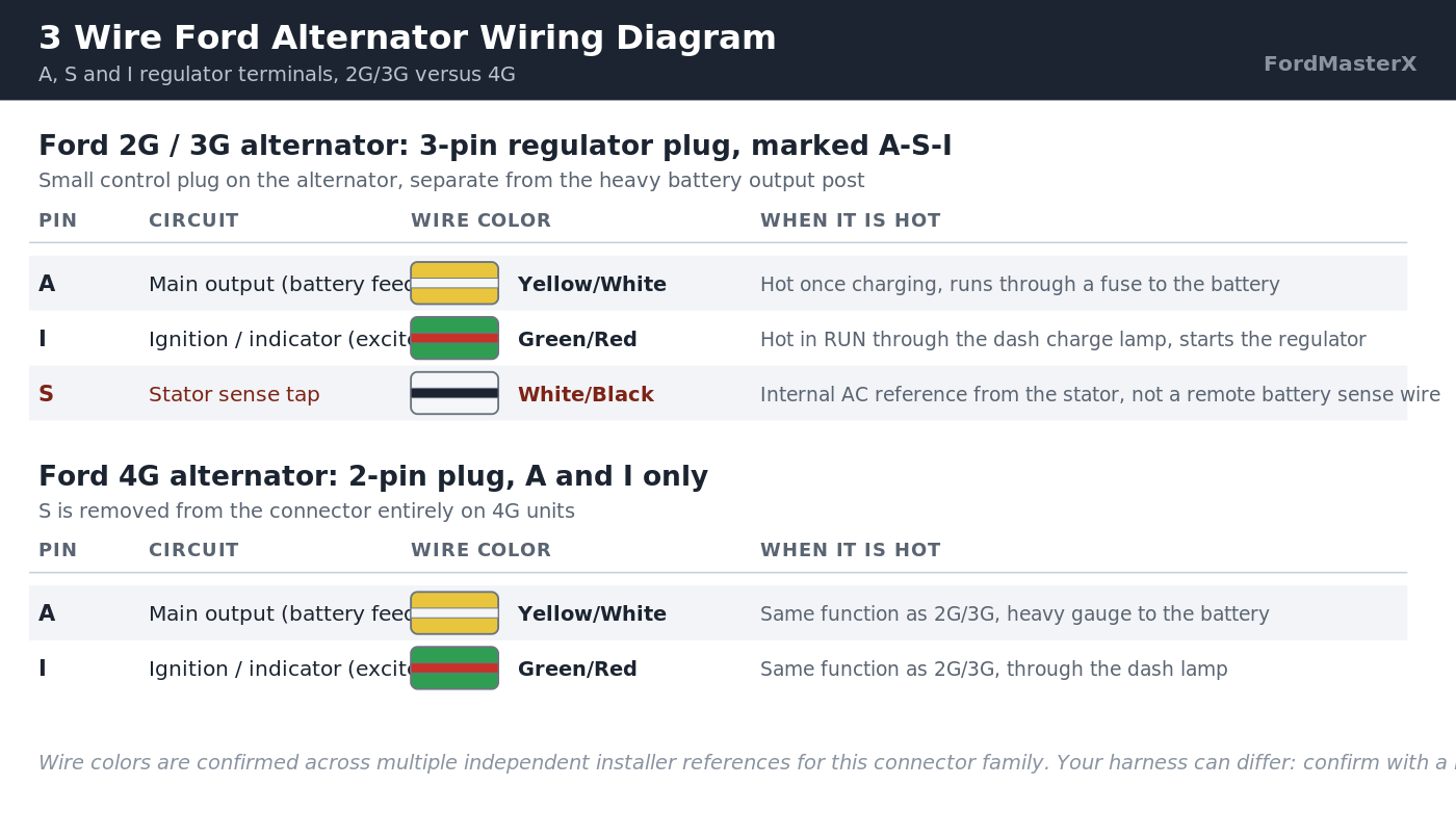
The full picture, not a selection. These colors come from multiple independent sources describing the same connector family, cited below. Confirm against your own harness with a multimeter regardless.
| Generation | Terminal | Function | Commonly documented color | Notes |
|---|---|---|---|---|
| 2G / 3G (3-pin A-S-I plug) | A | Main output, battery feed | Yellow with a white stripe | Heavy gauge, fuse it close to the battery |
| 2G / 3G (3-pin A-S-I plug) | I | Ignition / indicator (exciter) | Green with a red stripe | Through the dash charge lamp; add a resistor if there is no lamp |
| 2G / 3G (3-pin A-S-I plug) | S | Stator sense tap | White with a black stripe | Jumps to the alternator’s own stator plug, not a remote battery sense wire |
| 4G (2-pin A-I plug) | A | Main output, battery feed | Yellow with a white stripe | Same function and typical color as 2G/3G |
| 4G (2-pin A-I plug) | I | Ignition / indicator (exciter) | Green with a red stripe | Same function and typical color as 2G/3G |
| 4G (2-pin A-I plug) | S | Not present on this connector | Not applicable | Sensed internally through a regulator mounting screw, no external pin |
| 6G (OEM plug, regulator under rear cover) | A, I | Same two functions as above | Varies by model; factory plug is keyed | Use the factory connector; aftermarket pigtails are matched by plug shape, not color |
Five sources back this table: the12volt.com’s terminal ID thread, gt40s.com’s 3G wiring thread and stangnet.com’s 3G upgrade thread. Two more agree: classicbroncos.com’s 4G wiring thread and Engine Builder Magazine’s 4G breakdown.
3-wire alternator symptom to terminal guide
Readers usually arrive with a symptom, not a terminal letter. This maps the common ones.
| What is happening | Check this terminal |
|---|---|
| Dash charge light stays on, battery slowly goes dead | I: confirm it has switched 12V with the key in RUN |
| No output at all, alternator spins but battery never charges | A: check the fuse or fusible link and the output post for corrosion |
| Alternator whines, connector warm to the touch, intermittent charge | A: a loose or corroded output connection drops voltage and makes heat under load |
| Swapped in a 3G or 4G unit, charge light never goes out | I: the donor unit still needs switched ignition power, it is not self-powering |
| Regulator will not excite on a converted or rebuilt unit | S: confirm your regulator expects a stator tap and not a remote sense feed |
How to wire a 3-wire Ford alternator
Do this in order. Each step depends on the one before it.
- Identify your connector. Count the pins before touching a wire. Two pins means A and I only, no external S.
- Confirm each terminal with a multimeter before cutting or splicing anything. With the alternator unplugged and the key off, A should show continuity to the battery through its fuse.
- Run A to the battery through a fuse or fusible link rated for the alternator’s full output. Keep this wire short and heavy-gauge; it carries the full charging current.
- Run I to a switched ignition source, through the dash charge lamp if your vehicle has one. With no lamp in the circuit, add a resistor in series instead, commonly cited around 500 ohms.
- Wire S only if your connector has it. First confirm whether your regulator wants a factory stator tap or an aftermarket remote sense feed. These are not the same signal.
- Ground the case through a solid, clean mount or a dedicated ground strap. A weak case ground causes the same symptoms as a bad A or I connection.
- Start the engine and check voltage at the battery. A properly wired 3-wire alternator should settle between 13.8 and 14.4 volts within a minute or two of idle.
A loose output connection is the single most common cause of a warm connector on these alternators. Before replacing a unit that tests fine off the vehicle, pull and inspect the A connection first.
If the charging system still will not settle, stop swapping parts. Trace the circuit with a proper diagnostic tool instead of guessing.
A battery that keeps going flat from a miswired I circuit is worth a second look too. Check it against a battery sized correctly for your truck. A marginal battery makes a borderline charging problem look worse than it is.
For the parts: a mega fuse holder on the A wire protects the circuit like the factory fusible link did. A crimp connector and heat shrink kit makes a cleaner splice than tape.
Is the S terminal the same thing on every alternator?
No. On Ford’s own 2G/3G connector, S is a stator sense tap. It is an internal AC reference the regulator uses, not a measurement of battery voltage.
A MAHLE technical bulletin for a different alternator family uses the letter S for a battery-temperature sensor input. Same letter, different job, different brand.
Some aftermarket one-wire-to-three-wire conversion regulators relabel their third pin “S” too, for a true remote battery-voltage sense wire. If your kit’s instructions describe S as sensing battery voltage, you have an aftermarket regulator, not a stock Ford one. The table above does not apply to that pin.
What is the real difference between a 1-wire and 3-wire Ford alternator?
A 1-wire alternator is self-exciting. It only needs the A output connection and starts charging on its own once the engine spins it fast enough.
That is why hot-rod and restomod builds like it: one wire, nothing to the ignition switch.
A 3-wire alternator needs that ignition-fed I signal to start exciting the field. It typically reaches full output sooner and more consistently at idle. That is why most factory installs, and anyone keeping a working dash charge light, use the 3-wire design instead.
3-wire Ford alternator quick reference
The rows looked up most, in one place.
| Terminal | Also called | Typical wire color | Connects to |
|---|---|---|---|
| A | BAT, main output | Yellow/White | Battery positive, through a fuse |
| I | Ignition, indicator, exciter | Green/Red | Switched ignition power, through the dash lamp or a series resistor |
| S | Stator sense, field sense | White/Black | The alternator’s own stator plug, not a remote battery feed |
If your connector only has two pins, you have a 4G-style unit. Wire A and I exactly as above and skip S; there is nothing to connect it to.
This site’s 2G alternator wiring guide covers that earlier large-case design in more detail.