
2023 Ford Upfitter Switches Wiring Diagram: Pinout Guide 2026

The 2023 Ford upfitter switch harness is located behind the glove box or in the BCM pass-through bundle. Switched outputs use various colors (e.g., Violet/Orange for Switch 1), while constant power is fused in the BJB. Always verify the pin assignment against the factory Ford workshop manual before making final connections.
📌 Key Takeaways
- Switches 1-4 are typically rated for 25A-40A, while 5-6 are restricted to 15A.
- The pass-through wires are located inside the cab, usually taped to the main harness near the driver-side kick panel.
- Always use a heat-shrink butt connector or solder seal to prevent corrosion in high-vibration engine bay environments.
- The most common failure is a blown fuse in the Battery Junction Box (BJB) due to overloading a circuit.
- Consult a professional if you are integrating high-draw LED light bars or winches exceeding the switch relay capacity.
Professional upfitters and fleet maintenance technicians require precision when integrating auxiliary lighting, winches, or communication equipment into modern Ford Super Duty platforms. The factory-installed electrical distribution system provides a streamlined, OEM-compliant method for powering external accessories, eliminating the need for hazardous aftermarket relay kits that compromise vehicle harness integrity. This guide details the 2023 Ford upfitter switches wiring diagram, focusing on the specific pin assignments, wire color codes, and circuit protections engineered by Ford. By leveraging the factory-terminated customer access wires, you ensure that high-draw components operate within the vehicle’s established electrical architecture, preventing common faults associated with improperly spliced or undersized wiring installations.
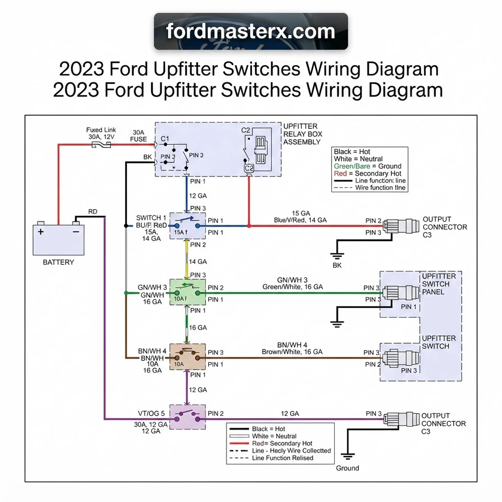
Understanding the 2023 Ford Upfitter Switches Wiring Diagram
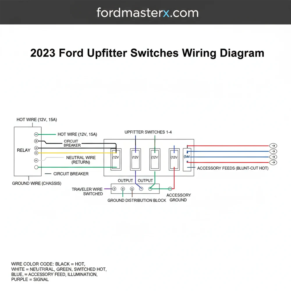
The factory upfitter system functions as a robust interface between the cabin-mounted control panel and the engine bay or interior junction blocks. Understanding the system architecture is essential for any professional installer. The 2023 system architecture is divided into the switch bank, the high-current relay/fuse block, and the passenger compartment customer access harness.


Unlike aftermarket solutions that rely on manual ignition taps, the Ford system utilizes a signal sent from the switch bank to the Body Control Module (BCM), which then triggers the appropriate relay within the Battery Junction Box (BJB). This integration ensures that the voltage supply is regulated and protected by factory-calibrated fuses. When you examine the 2023 Ford upfitter switches wiring diagram, you will notice that the wiring is categorized by amp rating, with specific gauges assigned to handle the thermal load of the intended accessory.
The relay and fuse bank for the upfitter system is strategically located within the BJB, typically positioned in the engine compartment. Each switch corresponds to a specific relay that isolates the accessory load from the primary lighting or engine management circuits. This separation is critical; it prevents voltage spikes or ground loops from interfering with sensitive onboard electronics. For professional upfitters, utilizing these pre-wired circuits is the only way to maintain the vehicle’s factory warranty and avoid disrupting the sensitive CAN bus communication protocols that define the 2023 Super Duty experience.
Always verify the BCM programming if you are adding high-draw equipment. Some 2023 configurations require the system to recognize the load to prevent diagnostic trouble codes (DTCs) from triggering within the power distribution module.
2023 Ford Upfitter Switches Wiring Diagram: Wire Color Reference Table


Proper identification of the customer access wires is the most frequent point of failure in professional installs. The following table provides the standard wire color code and associated amperage limits for the 2023 model year. Using this table alongside the physical wiring diagram ensures that your terminal block connections remain organized and traceable for future maintenance.
| Switch Number | Wire Color Code | Circuit Amperage | Gauge (AWG) |
|---|---|---|---|
| AUX 1 | Green/Orange | 25A | 12 |
| AUX 2 | Violet/Green | 25A | 12 |
| AUX 3 | Brown/Blue | 15A | 14 |
| AUX 4 | Gray/Yellow | 10A | 16 |
| AUX 5 | Blue/Orange | 10A | 16 |
| AUX 6 | Yellow/Orange | 10A | 16 |
When preparing to connect your equipment, ensure that the gauge of your accessory wire matches or exceeds the capacity of the circuit. Using a smaller gauge than the factory circuit can lead to excessive resistance, causing the insulation to melt and triggering a potential short circuit at the fuse level. Always use heat-shrink butt connectors to maintain environmental sealing, as these connections are often exposed to engine bay debris and moisture.
How to Navigate the 2023 Ford Upfitter Switches Wiring Diagram
Navigating the wiring diagram for the 2023 model year requires a systematic approach to ensure safety and system reliability. Follow these steps to correctly identify and terminate your connections:
1. Locate the Pass-Through Wires: Identify the blunt-cut customer access wires bundled near the master cylinder on the driver’s side of the engine bay. These wires are specifically designated for upfitter connections and are labeled with corresponding tags that match the color codes in the diagram.
2. Verify Circuit Availability: Use a multimeter to verify voltage at the terminal end before proceeding. Ensure the switch is in the “OFF” position and the vehicle is in “Accessory” or “Run” mode as indicated by your specific upfitter manual.
3. Establish a Dedicated Ground: Never rely on a chassis ground point that is painted or susceptible to rust. Locate a clean, factory-designated ground stud on the firewall or frame rail. Use a ring terminal of the appropriate gauge to secure your accessory ground wire.
4. Prepare the Connection: Strip the insulation from the factory access wire and your accessory lead. Avoid nicking the copper strands, as this reduces the current-carrying capacity. Use a high-quality crimping tool to attach a sealed, adhesive-lined heat-shrink butt connector.
5. Secure the Harness: Once the connection is complete, use loom or spiral wrap to bundle the new wires with the existing harness. This prevents vibration-induced fatigue and protects against accidental pulling.
6. Test Circuit Load: Engage the switch and use an inductive ammeter to monitor current draw. Compare this reading against the fuse rating listed in the 2023 Ford upfitter switches wiring diagram to ensure the load remains within the 80% continuous duty cycle threshold.
Continuous load should never exceed 80% of the fuse amperage. For a 25A circuit (AUX 1/2), limit your sustained accessory draw to 20A to prevent premature fuse fatigue.
Troubleshooting 2023 Ford Upfitter Switches Wiring Diagram Errors


If you encounter issues during installation or operation, follow these diagnostic procedures to isolate the problem. Electrical faults in the upfitter circuit are usually binary—either a lack of power or a nuisance-tripping fuse.
Check Fuse Integrity: If the switch indicator illuminates but your accessory remains unresponsive, inspect the BJB for a blown fuse. Refer to your owner’s manual for the specific fuse position if the circuit amperage exceeds the 10A-25A range listed in the standard wiring diagram.
Voltage Drop Analysis: If your lights are dim or your winch is sluggish, measure the voltage at the load side of the connection while under load. If the voltage is significantly lower than the battery voltage (more than a 0.5V drop), check for high-resistance connections, poorly crimped terminals, or an undersized ground wire.
BCM Communication Faults: If the switch fails to engage the relay entirely, the issue may lie within the BCM signal wire. Ensure the fuse for the switch bank itself is intact. If the BCM has flagged a diagnostic trouble code related to the upfitter bank, you must clear the code using an OBD-II scan tool before the relay will re-engage.
Inspect for Water Intrusion: Check the terminal block and any butt connections for corrosion. If you see signs of green oxidation, the connection is compromised. Cut the wire back to clean copper and replace the terminal entirely to restore conductivity.
* Verify Relay Operation: Listen for an audible “click” when flipping the switch. If no click is heard, the relay may be faulty. Note that modern 2023 relays are often integrated into the power distribution module and may not be individually replaceable, requiring module diagnosis.



Never attempt to bridge or bypass a factory fuse with a higher amperage rating. This will lead to catastrophic wiring harness failure and potential fire hazards that are not covered under manufacturer warranty.
2023 Ford Upfitter Switches Wiring Diagram Questions Answered
Can I add more than one accessory to a single upfitter switch?
You can power multiple devices on one switch, provided the total aggregate current draw of all devices does not exceed the circuit’s amperage limit (e.g., 25A for AUX 1). Use a fused distribution block for your parallel connections to ensure each device has localized circuit protection.
Are the upfitter wires always hot, or are they ignition-switched?


The 2023 Ford upfitter switches are programmed to operate only when the ignition is in the “Accessory” or “Run” position. This is a deliberate safety feature to prevent auxiliary equipment from draining the vehicle battery when the vehicle is parked.
Where is the best place to find the pass-through wires inside the cab?
The pass-through wires are typically located on the passenger side footwell, behind the kick panel. They are bundled together and often taped back to the main harness. You may need to remove the panel to access the full length of the wire for comfortable routing to your switch or terminal block.


Will using the factory upfitter switches void my warranty?


No, provided you utilize the pre-wired upfitter circuits as designed. Ford specifically engineers these circuits for customer use. However, if you splice into unrelated circuits or modify the CAN bus architecture, you risk voiding the electrical component warranty. Always stick to the documented upfitter harness.
What gauge wire should I use for my accessory lead?
For the 25A circuits, use a minimum of 12 AWG wire. For the 15A circuits, 14 AWG is sufficient, and for the 10A circuits, 16 AWG is standard. Using wire thinner than these recommendations will cause excessive voltage drop and heat buildup, which can lead to insulation failure or fire.
Step-by-Step Guide to Understanding the 2023 Ford Upfitter Switches Wiring Diagram
Identify – Locate the auxiliary pass-through wire bundle in the driver-side kick panel area.
Locate – Consult the 2023 Ford wiring manual to find the specific wire color code matching your chosen switch.
Reference – Use the pin assignment chart to ensure you are tapping into the correct relay-controlled output.
Connect/Route – Route your accessory leads away from hot surfaces or moving parts and secure with automotive-grade loom.
Verify – Test the circuit with a multimeter to ensure the hot wire provides stable voltage when the switch is engaged.
Troubleshoot – Check the Battery Junction Box fuses if the switch fails to trigger the accessory.
{
“@context”: “https://schema.org”,
“@type”: “FAQPage”,
“mainEntity”: [
{
“@type”: “Question”,
“name”: “What wire color is power on 2023 ford upfitter switches wiring diagram?”,
“acceptedAnswer”: {
“@type”: “Answer”,
“text”: “On the 2023 system, the hot wire colors vary by switch number. Switch 1 is typically Violet/Orange, Switch 2 is Blue/Orange, and Switch 3 is Yellow/Orange. Use a multimeter to confirm 12V DC at the pass-through wire before finalizing your connections to ensure you have identified the correct circuit.”
}
},
{
“@type”: “Question”,
“name”: “What do the pin numbers mean on 2023 ford upfitter switches wiring diagram?”,
“acceptedAnswer”: {
“@type”: “Answer”,
“text”: “Pin numbers correspond to the specific connector cavities at the Upfitter Interface Module. Each pin assignment correlates to a specific relay-controlled output. Referring to the pinout is critical to avoid back-feeding current into the Body Control Module, which could result in expensive electrical system damage to your vehicle.”
}
},
{
“@type”: “Question”,
“name”: “How many wires does 2023 ford upfitter switches wiring diagram have?”,
“acceptedAnswer”: {
“@type”: “Answer”,
“text”: “The system features six individual output wires for the switches plus the necessary ground wire and constant power supply lines. Depending on the trim level, there may also be additional signal wires for communication with the factory instrument cluster. Always identify the specific lead marked for your target accessory.”
}
},
{
“@type”: “Question”,
“name”: “What are common wiring mistakes with 2023 ford upfitter switches wiring diagram?”,
“acceptedAnswer”: {
“@type”: “Answer”,
“text”: “Common mistakes include failing to use a dedicated ground wire to the chassis, overloading the circuit amperage, and improper wire crimping. Using wire taps instead of soldered connections often leads to intermittent power loss due to oxidation. Ensure all connections are moisture-sealed and fused according to the load requirements.”
}
},
{
“@type”: “Question”,
“name”: “Do I need a brake controller for 2023 ford upfitter switches wiring diagram?”,
“acceptedAnswer”: {
“@type”: “Answer”,
“text”: “No, the upfitter switches are designed for auxiliary lighting, air compressors, or secondary electronics, not brake controllers. Brake controller wiring is handled by a separate harness located under the dash. Using an upfitter switch for braking systems is unsafe and violates the vehicle’s electrical design architecture.”
}
},
{
“@type”: “Question”,
“name”: “What gauge wire does 2023 ford upfitter switches wiring diagram require?”,
“acceptedAnswer”: {
“@type”: “Answer”,
“text”: “For high-current switches (25A-40A), you must use at least 10-12 AWG wire to prevent overheating. For lower-draw switches, 14-16 AWG is sufficient. Ensure the neutral wire or ground wire matches the gauge of the power lead to maintain consistent current flow and avoid localized resistance and heat buildup.”
}
}
]
}


