2014 Ford Fusion Fuse Box Diagram: Installation Setup 2026

The 2014 Ford Fusion features two main boxes: the Battery Junction Box (BJB) located in the engine compartment and the Body Control Module (BCM) in the passenger footwell. Refer to the interior lid mapping for specific 5A-60A fuse circuits. Always disconnect the negative battery terminal before handling high-amperage relays to prevent shorts.
📌 Key Takeaways
- The BJB contains high-current fuses ranging from 20A to 60A for powertrain and cooling systems.
- Identify specific circuits by cross-referencing the owner’s manual grid with the physical markings on the plastic cover.
- Standard battery terminal fasteners typically require a 10mm socket and should be tightened to a torque spec of 5 Nm.
- Corrosion at the fuse base is the most common failure point causing intermittent electrical faults.
- Seek professional diagnostic assistance if an OBD-II scanner indicates a persistent ECU communication error after verifying all fuses.
The 2014 Ford Fusion utilizes a complex power distribution network designed to manage high-load automotive systems while maintaining precise communication between the powertrain control module and auxiliary electronics. Understanding the 2014 ford fusion fuse box diagram is essential for any technician tasked with diagnosing intermittent electrical failures, sensor malfunctions, or parasitic drains. This vehicle employs two primary power distribution centers: the Battery Junction Box (BJB) located in the engine compartment and the Body Control Module (BCM) located within the passenger cabin. Mastery of these distribution hubs allows for rapid identification of localized shorts or relay failures that often trigger erroneous dashboard indicators. Proper interpretation of these layouts is a prerequisite for effective electrical troubleshooting in modern Ford platforms.

Prime for Young Adults — 6 Months Free
Students and 18–24s get six months of Prime free, then half price.
Start 6 Months Free As an Amazon Associate I earn from qualifying purchases.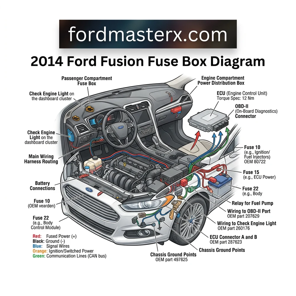
2014 Ford Fusion Fuse Box Diagram: Component Identification
Recommended Best Deal Products


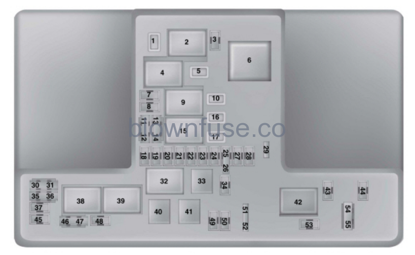
The electrical architecture of the 2014 Ford Fusion is divided into two primary zones. The Battery Junction Box (BJB), situated in the engine bay, acts as the gateway for main power distribution from the alternator and battery, protecting high-amperage circuits such as the cooling fan, starter solenoid, and ABS module. Conversely, the Interior Junction Box, governed by the Body Control Module (BCM), manages low-amperage logic circuits, cabin lighting, infotainment, and the OBD-II port interface.
Technicians must distinguish between the BJB’s high-current fuses (often bolt-down style or large “maxi” fuses) and the standard blade-type fuses used in the BCM. Failure to differentiate these can lead to improper component protection. Below is a breakdown of key electrical distribution centers.
| Component Location | Primary Function | Key Circuits Managed |
|---|---|---|
| Battery Junction Box (Engine Bay) | Main Power Distribution | Cooling Fans, ECU, PCM, ABS/ESC |
| Body Control Module (Cabin) | Signal/Logic Distribution | SYNC, OBD-II, Lighting, Instrument Cluster |
| Power Distribution Relays | High-Load Switching | Fuel Pump, Starter, A/C Compressor |
When referencing the 2014 ford fusion fuse box diagram, focus on the specific relay terminal positions. Many intermittent electrical issues stem from relay “pitting” or contact oxidation rather than a blown fuse. Before replacing components, ensure that you are verifying voltage at the load side of the relay terminal using a digital multimeter (DMM). When dealing with engine management components, keep in mind that the PCM draws power through specific fused rails. If these rails are compromised, you may encounter a no-start condition or a lack of communication with your scan tool when attempting to retrieve diagnostic codes.
Always cross-reference the diagram against your specific trim level. Ford produced multiple wiring harness configurations for the 2014 model year, including distinct layouts for the 1.5L, 2.0L EcoBoost, and 2.5L Duratec engines.
Common 2014 Ford Fusion Fuse Box Diagram Issues and Symptoms
Identifying electrical faults requires correlating symptoms to specific fuse circuits. A blown fuse is almost always a secondary symptom of an underlying electrical failure. When you observe a specific failure, refer to the diagram to see which components share that circuit.
Ford SYNC System Failure: Often caused by a blown fuse in the BCM. Before condemning the APIM (Accessory Protocol Interface Module), verify power at the module connector to ensure the fuse has not bypassed due to a software-induced surge.
Diagnostic Trouble Codes (DTCs): If your scan tool reports a “Communication Error,” check the fuses associated with the OBD-II port and the Data Link Connector (DLC). These are often shared with the cigar lighter or accessory power circuits.
Check Engine Light (CEL): If the CEL illuminates concurrently with multiple module warnings, inspect the BJB for moisture intrusion. The 2014 Ford Fusion is known for occasional water ingress near the cowl area, which can corrode fuse terminals and cause false signals.
Short-to-Ground Conditions: If a fuse blows immediately upon replacement, you have an active short. Common locations include the wiring harness chafing near the cooling fan shroud or the fuel pump assembly wiring near the tank top.
* Open Circuits: If a device fails but the fuse tests as “good,” suspect a relay failure. Swap identical relays (e.g., A/C relay with horn relay) to verify if the component function returns.
Understanding the relationship between the fuse panel and vehicle sensors is critical. For instance, an oil pressure sensor fault will not typically blow a fuse, but if the sensor shorts internally, it can damage the BCM logic board. If you see erratic readings for coolant flow or oil pressure, verify the sensor ground wire integrity before assuming a fuse-related failure.
Diagnostic Steps for 2014 Ford Fusion Electrical Faults
Recommended Best Deal Products

To perform a professional-grade diagnosis, you must utilize a structured approach. Never rely on visual inspection alone; small “hairline” cracks in fuse elements can be invisible to the naked eye.
1. Verification: Confirm the specific symptom. If the vehicle is throwing a diagnostic code related to the ECU or powertrain, verify the fault using an OBD-II scan tool before pulling fuses.
2. Circuit Identification: Utilize the 2014 ford fusion fuse box diagram to identify every fuse or relay associated with the malfunctioning system.
3. Voltage Drop Testing: With the fuse removed, use a DMM to measure voltage on both the supply and load sides. A supply-side voltage drop indicates a failing wire or corroded connection before the power reaches the fuse.
4. Continuity Check: Ensure the load side of the circuit is not grounded to the chassis using an ohmmeter. If the circuit shows low resistance to ground (zero ohms), a short exists.
5. Component Isolation: Disconnect the end-load component (e.g., the fuel pump or cooling fan). If the short persists, the fault lies within the harness; if it clears, the component itself is faulty.
6. Amperage Validation: When replacing fuses, match the OEM amperage rating exactly. Using a higher-rated fuse can result in catastrophic harness melting during an over-current event.

Audible — Listen Free for 30 Days
One free credit a month and thousands of titles included.
Listen Free for 30 Days As an Amazon Associate I earn from qualifying purchases.Never use a “jumper” wire or a fuse with a higher rating than specified in the owner’s manual. This overrides the vehicle’s inherent fire protection and can lead to thermal runaway in the fuse box PCB.
If you are investigating timing chain issues or major engine mechanical failures, remember that these are rarely related to fuse box faults. While the ECU manages timing through solenoid control, fuse failure would manifest as a complete engine stall or a “no crank” condition, not a mechanical synchronization error.
Preventing Electrical Damage in Your 2014 Ford Fusion
Long-term electrical health depends on maintaining the integrity of the fuse box environmental seals. The 2014 Ford Fusion’s engine bay is subject to significant thermal cycling, which can degrade the plastic housing of the BJB over time. Ensure the cover is properly latched to prevent moisture and road salt from accelerating terminal corrosion.
When performing unrelated maintenance, such as checking the coolant flow or performing an oil change, inspect the surrounding wire looms. Heat-damaged insulation near the engine block is a frequent cause of intermittent shorts that eventually manifest as blown fuses. Furthermore, avoid “back-probing” connectors with oversized multimeter leads, as this can permanently stretch the pin receptacles, creating high-resistance connections that generate excess heat.
If you find it necessary to remove the ECU or BCM, ensure all grounding straps are clean and torqued to manufacturer specifications. Loose grounds are a leading cause of “ghost” codes that mimic electrical shorts.
Regularly scanning the vehicle with an OBD-II tool for pending diagnostic codes can provide early warning of electrical instabilities. Even if the check engine light is off, an “intermittent communication” code stored in the PCM often suggests a loose relay or a corroded fuse terminal that hasn’t failed fully yet. Taking proactive steps to clean your electrical contacts using an electronic-grade cleaner will extend the life of your vehicle’s logic and power systems.
2014 Ford Fusion Fuse Box Diagram Questions Answered
Recommended Best Deal Products


Where is the 2014 Ford Fusion interior fuse box located?
The interior fuse box, often called the Body Control Module (BCM) junction box, is located behind the glove box compartment in the passenger side footwell. You must release the glove box dampener to access the panel.
Can I use an LED-lit fuse in my 2014 Ford Fusion?
While LED fuses are convenient for rapid visual identification, they are generally not recommended for sensitive ECU-controlled circuits. The internal resistance of the LED can occasionally trigger false “low voltage” or “circuit fault” codes in highly sensitive modules.
Does the 2014 ford fusion fuse box diagram cover the fuel pump?
Yes, the fuel pump relay and fuse are housed within the engine bay Battery Junction Box (BJB). If you are experiencing a no-start condition, check the BJB diagram first before testing the fuel pump assembly.
Why does my fuse box smell like burnt plastic?
A burning smell near the fuse box indicates an high-resistance connection, likely caused by a loose fuse terminal or a corroded relay blade. This creates heat that can melt the plastic housing. Disconnect the battery immediately and inspect the affected terminal for signs of thermal melting.
Audible Premium Plus — Annual Membership
12 audiobook credits up front, plus the full Audible catalogue.
See Annual Plans As an Amazon Associate I earn from qualifying purchases.How do I test a relay from the 2014 ford fusion fuse box diagram?
You can test a relay by applying 12V to the coil pins (usually pins 85 and 86) and listening for an audible “click.” Simultaneously, check for continuity between the load pins (30 and 87) using a multimeter. If the relay clicks but does not show continuity across the load pins, the contact points are pitted and the relay must be replaced.
Step-by-Step Guide to Understanding the 2014 Ford Fusion Fuse Box Diagram
Identify – Locate the fuse box cover and cross-reference the diagram symbols with your vehicle’s specific engine trim.
Locate – Gain access to the engine BJB or interior BCM by releasing the plastic tabs using a flat-head screwdriver.
Reference – Use the diagram to pinpoint the exact fuse number linked to your malfunctioning component.
Connect – Insert an OBD-II scanner into the diagnostic port to clear existing codes after replacing a faulty fuse.
Verify – Start the engine and confirm the check engine light is cleared and all electrical accessories are functioning.
Troubleshoot – If the issue persists, inspect relay sockets for heat damage or loose pins requiring professional electrical repair.