2008 Ford F150 Fuse Box Diagram: 2026 Troubleshooting Guide

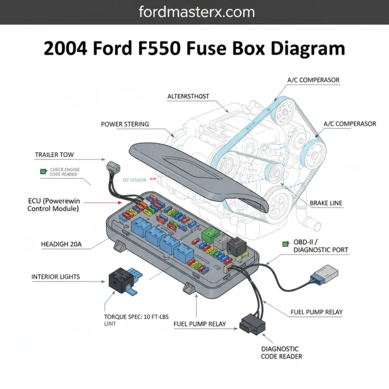
The 2008 Ford F150 features a Power Distribution Box in the engine compartment (driver side) and a Passenger Compartment Fuse Panel located in the passenger side kick panel. These house essential circuits for the ECU and OBD-II port, typically utilizing standard ATO/MINI blade fuses ranging from 5A to 60A.
📌 Key Takeaways
- The Battery Junction Box (BJB) houses high-amperage fuses up to 60A for engine management systems.
- Verify circuit integrity by cross-referencing your specific trim level’s diagram, as engine options dictate relay layouts.
- Always adhere to factory torque specs of 12-15 Nm if removing mounting brackets to avoid damaging the plastic housing.
- A recurring blown fuse in the OBD-II circuit often indicates a short in the auxiliary accessory wiring or a failing ECU module.
- If a circuit repeatedly fails after replacement, consult a professional to perform a voltage drop test on the wiring harness.
Understanding the electrical architecture of your truck is essential for maintaining vehicle health and preventing catastrophic failure. Whether you are addressing an intermittent check engine light or diagnosing a complete power loss, accessing an accurate 2008 Ford F150 fuse box diagram is the first step in any professional diagnostic workflow. The 2008 model year utilizes a complex Power Distribution Box and a Passenger Compartment Junction Box to manage the high-current demands of the ECU and auxiliary equipment. By mastering these schematics, you can pinpoint electrical shorts, avoid unnecessary component replacement, and ensure your vehicle remains within factory operating parameters for long-term reliability.

Prime for Young Adults — 6 Months Free
Students and 18–24s get six months of Prime free, then half price.
Start 6 Months Free As an Amazon Associate I earn from qualifying purchases.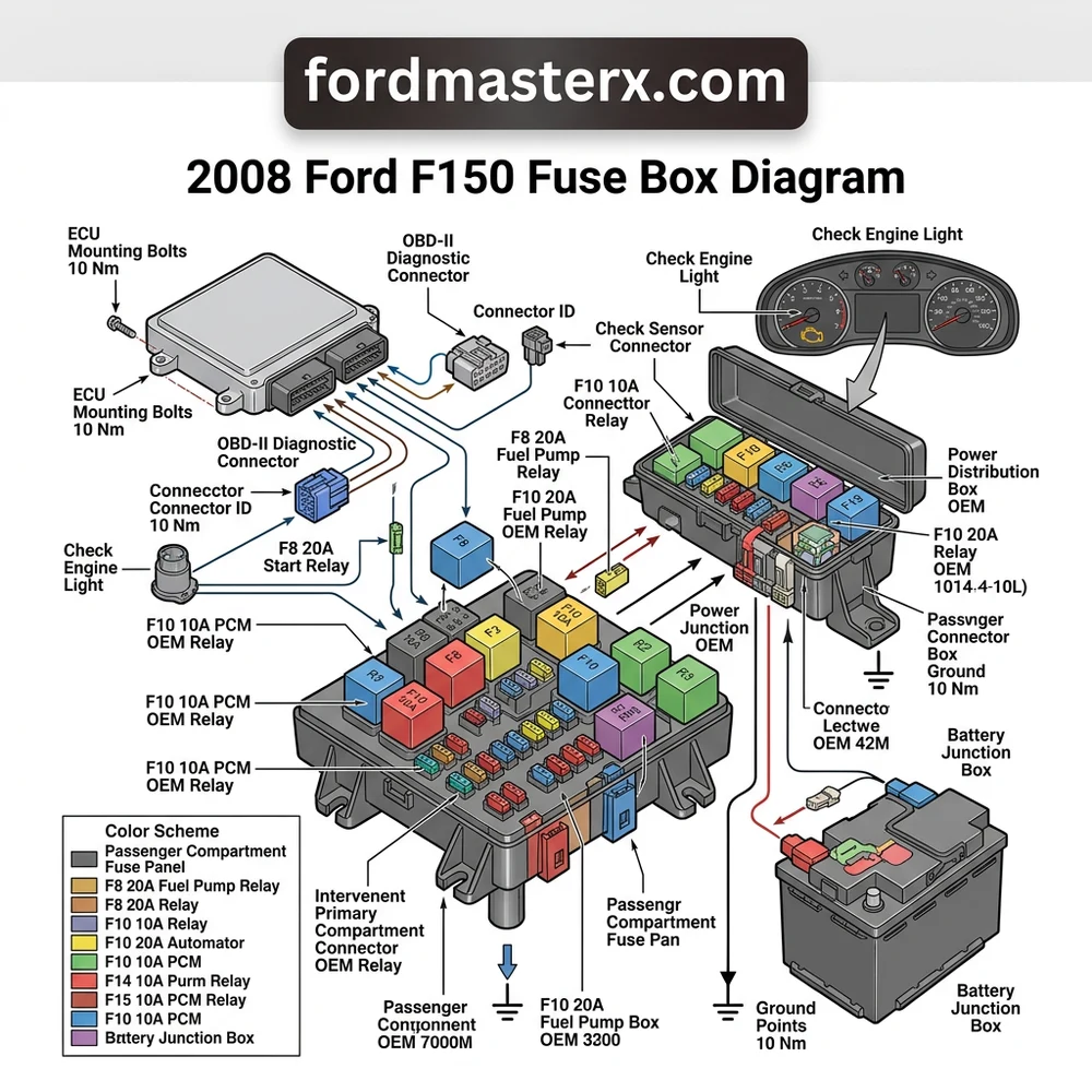
Locating and Accessing the 2008 Ford F150 Fuse Box Panels
Recommended Best Deal Products


Modern F-series trucks employ a dual-panel electrical architecture designed to isolate high-amperage engine components from interior cabin electronics. Accessing these panels requires care to avoid damaging the plastic retaining clips or the surrounding trim materials, which can become brittle after years of thermal cycling.
Passenger Compartment Junction Box Accessibility

The interior fuse panel is located in the passenger-side footwell, concealed behind the kick panel trim. To access this unit, you must disengage the plastic cover by depressing the primary latch located at the top center. Once removed, you will see a comprehensive layout that governs interior lighting, radio functionality, and the OBD-II diagnostic port power supply. Ensure the ignition is switched to the OFF position before manipulating any fuses to prevent electrical spikes that could damage sensitive ECU pins. Always inspect the reverse side of the cover for the printed reference guide, though verify it against your official 2008 Ford F150 fuse box diagram to account for trim-level variations such as Lariat, XLT, or FX4 packages.
Power Distribution Box Engine Bay Procedures
The second panel, known as the Power Distribution Box, is housed within the engine compartment on the driver’s side fender apron. This unit manages the heavy-duty circuits, including the cooling fan, fuel pump, and starter solenoid. To remove the lid, rotate the locking tabs 90 degrees. Avoid using metallic tools that could bridge connections across the bus bars, which could cause a dead short and permanent damage to the harness. If you detect an abnormal scent of ozone or charred plastic in this area, perform a visual inspection for melted relay housings, as these often indicate a pending failure of the timing chain cover gasket or oil pressure switch harness routing that has compromised the electrical integrity of the bay.
Never replace a fuse with a higher amperage rating than specified. Using a 30A fuse in a 15A slot creates a fire hazard as the wiring harness is not rated for the increased current load, potentially causing the insulation to melt and damaging the ECU.
2008 Ford F150 Fuse Box Diagram: Component Reference Table
The following table serves as a technical summary for standard electrical circuits. Note that manufacturer specifications may vary based on engine displacement (4.2L, 4.6L, or 5.4L Triton).
| Circuit Function | Amperage | Fuse Type |
|---|---|---|
| PCM / ECU Power | 20A | Mini |
| Fuel Pump Relay | 20A | Mini |
| OBD-II / Data Link | 15A | Mini |
| Cooling Fan Control | 40A | Maxi |
| Ignition Switch | 30A | Maxi |
| ABS Module | 50A | Maxi |
| Headlamp Relay | 20A | Mini |
When referencing the 2008 Ford F150 fuse box diagram, focus on the specific relay positions for the fuel pump and powertrain control module (PCM). A failure in the relay coil can mimic symptoms of a bad fuel pump, leading to incorrect diagnostic paths. Verify resistance across the relay pins using a digital multimeter (DMM) set to the 200-ohm scale; a reading outside of OEM specifications (typically 70-90 ohms for standard relays) indicates a failing component.
Common Symptoms of 2008 Ford F150 Electrical Failures
Recommended Best Deal Products


Electrical system irregularities in the 2008 F150 frequently manifest as a combination of drivability issues and warning indicators. It is vital to distinguish between a localized fuse failure and a deeper hardware issue, such as a clogged oil pressure screen affecting VVT solenoids or a malfunctioning timing chain tensioner.
Diagnostic Code Interfacing and ECU Behavior
If your vehicle triggers a check engine light accompanied by a P0606 (PCM Processor Fault) or P0231 (Fuel Pump Secondary Circuit Low), do not immediately assume the ECU is dead. These codes often stem from corroded fuse contacts in the Power Distribution Box. Moisture ingress, common in older F150 models, can oxidize pins, increasing resistance. If your diagnostic scan tool fails to communicate with the ECU through the OBD-II port, check the cigarette lighter/auxiliary power fuse first, as these circuits often share a power supply with the diagnostic data bus.
Correlation Between Sensors and Electrical Loads
Erratic oil pressure readings or sudden changes in coolant flow efficiency can sometimes be traced back to grounding issues. The vehicle harness utilizes a complex ground scheme. If the main strap between the chassis and engine block is compromised, current will seek an alternative path, often through small-gauge sensor wires. This can burn out sensor ground circuits inside the ECU. Before blaming the ECU, verify that your electrical loads—such as power windows or cooling fans—are not causing excessive voltage drops during high-current draw cycles, which could indicate a dying alternator or a shorted relay coil.

Audible — Listen Free for 30 Days
One free credit a month and thousands of titles included.
Listen Free for 30 Days As an Amazon Associate I earn from qualifying purchases.For troubleshooting intermittent electrical gremlins, use a voltage drop test. Place your multimeter leads across the fuse terminals while the circuit is active. A reading higher than 0.1V suggests high resistance or a deteriorating fuse link, necessitating immediate replacement.
Diagnosis Steps for 2008 Ford F150 Fuse Box Problems
Approaching a suspected electrical fault requires a structured, scientific method. Following these steps ensures you do not inadvertently exacerbate the issue or cause a secondary fault in the vehicle’s electrical system.
1. Verify Power at Source: Connect a DMM to the battery terminals to ensure a base voltage of 12.6V. If the battery is under 12.2V, charge it fully before conducting further diagnostics, as low voltage can trigger false diagnostic codes.
2. Visual Inspection for Continuity: Using a fuse puller, extract the suspected fuse and inspect the internal metal filament. A “blown” fuse will show an obvious gap. However, perform a continuity check with a multimeter; some cracks are microscopic and invisible to the naked eye.
3. Check for Short-to-Ground: If a fuse blows immediately upon replacement, you have a hard short. Disconnect the load (e.g., the fuel pump or cooling fan). If the new fuse holds, the fault lies within the component itself. If it continues to blow, the wiring harness between the fuse box and the component is compromised.
4. Relay Swap Analysis: If a component fails to actuate, swap a known-good relay of the same part number from a non-critical circuit (like the horn or interior fan) into the problematic slot. If the component engages, replace the faulty relay.
5. Inspect Terminal Pins: Examine the female slots in the fuse box. If they appear “widened” or discolored from heat, the tension is lost, leading to poor connection. Apply a dielectric contact cleaner to remove oxidation and use a thin needle tool to gently tension the terminals.
Always observe the proper torque spec when re-securing any ground straps associated with the fuse panel—typically 15-18 Nm depending on the bolt size—to ensure low-resistance connectivity.
2008 Ford F150 Fuse Box Diagram Questions Answered
Recommended Best Deal Products


Can I use a higher amperage fuse if a 15A keeps blowing?
No. The fuse acts as a safety device for the wiring harness. Replacing a 15A with a 20A or 30A fuse will allow more current to flow than the wires are designed to handle. This will likely cause the wiring insulation to melt, potentially leading to an engine bay fire. Investigate the cause of the short instead.
Why does my OBD-II port have no power?
Power for the OBD-II port is often tied to the cigarette lighter or auxiliary power point circuits. Check your 2008 Ford F150 fuse box diagram for the interior panel to find the dedicated power point fuse (often a 20A mini fuse). If this fuse is blown, the scanner will not receive power to initialize its handshake with the ECU.
Is it normal for relays in the engine bay to feel hot?
Relays generate heat during operation, especially those handling high-current components like cooling fans or fuel pumps. However, they should never be “too hot to touch.” If the housing is soft, deformed, or shows signs of burning, the relay has high internal resistance and should be replaced immediately to prevent terminal melting.
How do I know if the fuse box itself is faulty?
Internal failure of the power distribution box is rare but possible. Symptoms include localized melting, multiple unrelated circuits failing at once, or “ghost” voltage readings across terminals that should be isolated. If you have ruled out wiring shorts and bad relays, inspect the circuit board beneath the fuse panel for signs of water intrusion or burned traces.
Does the timing chain or oil pressure sensor affect fuse function?
No, they are independent systems. However, a failing timing chain tensioner or oil pressure switch can cause the engine to misfire or run poorly, which will illuminate the check engine light. Mechanics often confuse these mechanical issues with electrical ones because the symptoms—rough idling or limp mode—are similar. Always differentiate between electrical failures and mechanical performance issues by checking for diagnostic codes first.
Step-by-Step Guide to Understanding the 2008 Ford F150 Fuse Box Diagram
Identify – Access the fuse box cover and cross-reference the imprinted code with the digital diagram.
Audible Premium Plus — Annual Membership
12 audiobook credits up front, plus the full Audible catalogue.
See Annual Plans As an Amazon Associate I earn from qualifying purchases.Locate – Find the specific circuit corresponding to your malfunctioning system, such as the fuel pump or OBD-II port.
Reference – Use the diagram to confirm the correct fuse amperage rating and type before removal.
Route – If testing wiring, route multimeter probes into the fuse slots carefully without bending the contact pins.
Verify – Insert a new fuse, clear any stored diagnostic code, and verify the system function with a scan tool.
Troubleshoot – If the fuse blows again immediately, inspect the downstream wiring harness for insulation wear or shorts.