
2007 Ford Escape Fuse Box Diagram: 2026 Troubleshooting Guide

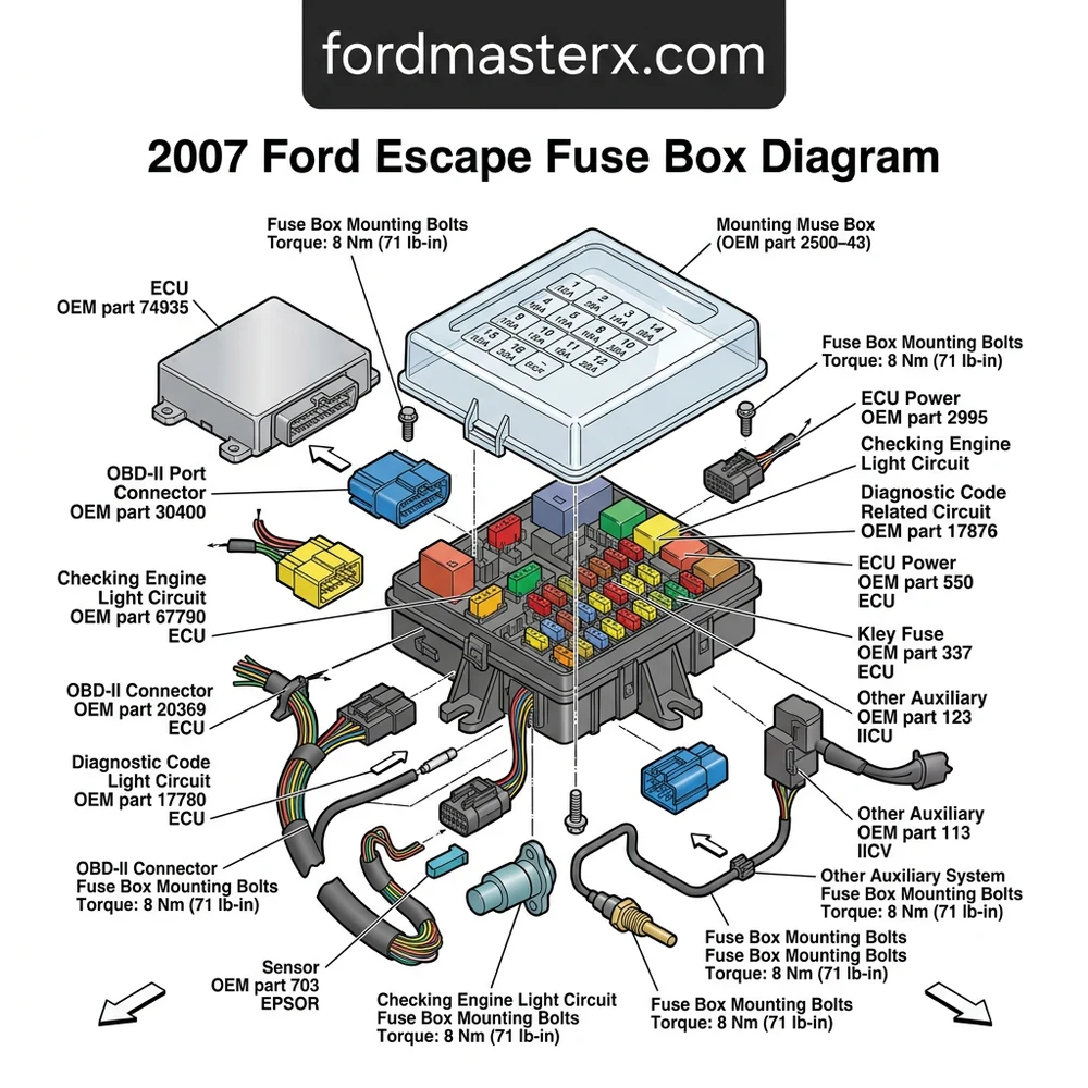
The 2007 Ford Escape features two fuse blocks: the Battery Junction Box (BJB) located in the engine bay near the driver-side fender, and the Smart Junction Box (SJB) in the passenger-side kick panel. The SJB controls the ECU logic and OBD-II port power, typically on a 15A mini fuse.
📌 Key Takeaways
- The BJB houses high-amperage relays ranging from 20A to 60A for powertrain protection.
- Always confirm the exact fuse location via the molded map on the interior cover.
- Tighten ground cables to 12 Nm torque spec to prevent voltage drop and intermittent ECU resets.
- A blown 15A fuse in the SJB is the most common cause of OBD-II scanner communication failure.
- Consult an ASE-certified technician if the check engine light persists after replacing a confirmed blown fuse.
For professional technicians and advanced DIY enthusiasts, navigating the electrical architecture of the 2007 Ford Escape is essential for resolving complex diagnostic challenges. The vehicle utilizes a sophisticated two-tier power distribution network, split between the high-amperage Power Distribution Box and the interior Smart Junction Box. When performing deep-level diagnostics—whether troubleshooting a persistent check engine light, analyzing an ECU communication failure, or tracing a parasitic battery draw—accessing an accurate 2007 Ford Escape fuse box diagram is the primary prerequisite. This guide provides the technical specificity required to map circuit paths, identify relay functions, and restore electrical integrity to the vehicle’s control modules, fuel system, and auxiliary components.
Locating the 2007 Ford Escape Fuse Box Diagram Locations

The 2007 Ford Escape electrical system is bifurcated to separate high-current ignition and charging circuits from low-current logic and lighting controls. Understanding the physical geography of these modules is the first step in effective troubleshooting. The primary hub, known as the Power Distribution Box (PDB), is located under the hood on the driver-side inner fender apron, protected by a high-impact plastic housing. This box contains the high-amperage fuses and relays responsible for engine management, cooling fans, and the alternator circuit.


Mapping the Engine Bay Power Distribution Box

To access the PDB, you must release the spring-loaded clips on the periphery of the cover. Ensure the ignition is in the OFF position and the negative battery terminal is disconnected before probing any high-current terminals. This module houses essential components including the ECU power relay, fuel pump relay, and the main ignition switch supply. Within the 2007 Ford Escape fuse box diagram, you will find color-coded slots corresponding to micro, mini, and J-case fuses. Technicians should note that corrosion on these terminal blocks is common in high-humidity climates, which can lead to intermittent voltage drops affecting sensor inputs like oil pressure or coolant flow sensors.
Accessing the Passenger Compartment Smart Junction Box


The secondary electrical hub, the Smart Junction Box (SJB), is located in the passenger-side footwell, behind the kick panel. This module manages cabin electronics, including the instrument cluster, power windows, and the OBD-II port. If you are attempting to clear a diagnostic code or monitor live data streams, the SJB is the primary distribution point for the data link connector. Unlike the PDB, the SJB is highly sensitive to moisture ingress from the windshield cowl drain. Before replacing components labeled in the 2007 Ford Escape fuse box diagram for the interior, perform a visual inspection for green oxidation on the terminal pins, which indicates a breach in the cabin seal.
| Module | Primary Function | Accessible Components |
|---|---|---|
| PDB (Engine) | High Current Loads | ECU, Fuel Pump, Radiator Fan |
| SJB (Interior) | Logic & Cabin Control | OBD-II, Cluster, Door Locks |
Common 2007 Ford Escape Electrical Issues and Symptoms


Failure to correctly diagnose electrical faults often leads to “part-swapping” rather than precise repair. A blown fuse rarely acts in isolation; it is frequently the result of a downstream short circuit or a failing component drawing excessive current. When a check engine light illuminates, the ECU logs a specific diagnostic code (DTC). If this code relates to a circuit performance issue—such as an O2 sensor heater circuit or a purge valve malfunction—cross-referencing the fuse box diagram is mandatory before testing the actual sensor. Ignoring these electrical precursors can lead to collateral damage, such as restricted coolant flow due to fan relay failure or inaccurate oil pressure readings caused by grounded harness wiring.
Always check for heat-damaged plastic around the fuse terminal. If the fuse block shows signs of melting, the internal resistance is likely too high, necessitated by a loose terminal grip. Cleaning the terminal with electronic contact cleaner is insufficient; the terminal tension must be restored to OEM spec.
Analyzing Symptoms of Blown Fuses
- Engine Cranking but No Start: Often traced to the fuel pump relay or the PCM power circuit fuse in the engine bay PDB.
- Unresponsive OBD-II Port: Usually indicates a blown fuse in the interior SJB affecting the cigarette lighter or auxiliary power point, which often shares a power feed with the diagnostic port.
- Erratic Instrument Cluster: Flickering lights or dead gauges often point to a ground distribution fault or a failing relay inside the interior junction box.
- Coolant Overheating: Frequently caused by a blown high-amperage cooling fan fuse or a relay that has failed in the closed position, which can be verified using a multimeter.
Step-by-Step 2007 Ford Escape Fuse Box Diagram Diagnosis
To execute a professional-grade diagnosis, you must utilize a high-impedance digital multimeter (DMM). Never use a test light on modern ECU-controlled circuits, as the spike in current can damage delicate logic gates. Following the 2007 Ford Escape fuse box diagram requires a systematic approach to isolate the load and test for voltage continuity across the fuse terminals. If you are investigating a timing chain rattle or oil pressure issues, ensure the electrical system is operating within the 13.5v to 14.5v range. Low voltage supplied to the Variable Valve Timing (VVT) solenoid, managed by the ECU, can often mimic mechanical timing issues by causing improper oil pressure modulation.
When removing high-amperage fuses or relays, ensure the vehicle is completely cold. Touching hot coolant lines or engine components during electrical testing is a significant burn risk. Use insulated pliers for J-case fuse extraction to avoid accidental shorting against the vehicle frame.
Protocol for Testing Circuit Continuity


- Verify the Diagnostic Code: Use an OBD-II scanner to pull specific codes. If the code mentions “Circuit Low,” search the 2007 Ford Escape fuse box diagram for the power feed supplying that sensor.
- Load Testing the Fuse: With the fuse installed, set your DMM to DC millivolts (mV). Place the probes on the two small test points found on the top of the fuse. A reading above 0.2mV typically indicates an open or high-resistance fuse that requires replacement.
- Relay Inspection: If a relay is suspected, swap it with an identical part number from a non-critical circuit, such as the horn or accessory lights, to confirm functionality.
- Inspecting Terminal Corrosion: If a fuse is intact but no power is present at the load, inspect the back of the junction box for pushed-out pins or corroded wiring.
Tools Required for Electrical Repairs
For precise work on the 2007 Ford Escape, maintain these tools:
Digital Multimeter with 10M-ohm input impedance;
Non-marring trim panel tools for SJB access;
Electronic contact cleaner (non-residue);
Torque wrench capable of 5-15 Nm for grounding strap connections;
Standard fuse puller set (various sizes).
2007 Ford Escape Fuse Box Diagram Questions Answered


Can a faulty relay cause a check engine light?


Yes. If a relay controlling a critical engine component, such as the ECU or the MAF sensor, develops a high-resistance contact point, the resulting voltage drop will trigger a diagnostic code. Always check the PDB according to the 2007 Ford Escape fuse box diagram before replacing expensive sensors.
Does the fuse box diagram indicate the torque spec for battery terminals?
The diagram itself focuses on electrical distribution. However, battery terminal connections must be secured to 8–10 Nm. Poor connections here often lead to erratic behavior in the electrical system, causing fuses to appear blown or relays to chatter during cranking.
Why does the OBD-II port show no communication with my scan tool?
This is frequently caused by a blown cigarette lighter fuse in the interior SJB. Since the data link connector shares a circuit with the accessory power outlet on many 2007 Ford Escape models, the absence of 12V power at the port renders diagnostic scanners unable to handshake with the ECU.
How do I distinguish between a bad ground and a blown fuse?
Use your multimeter to measure voltage drop between the negative battery terminal and the device casing. If the drop exceeds 0.5V, you have a ground distribution fault. A blown fuse, conversely, will show a complete loss of voltage on the load side of the circuit, as verified by the 2007 Ford Escape fuse box diagram.


