
2006 Ford Focus Fuse Box Diagram: Troubleshooting Guide (2026)

The 2006 Ford Focus features two main fuse panels: the Battery Junction Box in the engine compartment and the Passenger Compartment Fuse Panel located behind the glove box. Use the diagram to identify fuse amperage ratings, ranging from 5A to 60A, to resolve power delivery issues affecting the ECU and diagnostic systems.
📌 Key Takeaways
- The engine bay box contains high-amperage relays and fuses for the cooling fan and alternator, often rated at 40A to 60A.
- Always use a plastic puller tool; never use metal pliers, as this can cause a short circuit across sensitive ECU power pins.
- Ensure the ignition is in the OFF position before removing any fuse to prevent arching or electrical damage to the OBD-II module.
- Corrosion on the fuse box terminals is the most common failure point for intermittent ‘check engine light’ triggers.
- Seek professional diagnostic help if you detect burning plastic odors or if multiple system diagnostic codes persist after fuse replacement.
Managing the electrical health of a mid-2000s vehicle requires precise technical documentation, especially when dealing with intermittent failures in the 2006 Ford Focus. The vehicle utilizes two primary power distribution centers, each serving critical systems ranging from the Engine Control Unit (ECU) to passenger comfort features. Understanding the 2006 Ford Focus fuse box diagram is not merely about finding a blown element; it is an essential diagnostic practice for technicians aiming to isolate electrical shorts, parasitic battery draws, or communication failures between modules. This guide provides the technical breakdown necessary to navigate both the Battery Junction Box and the Central Junction Box, ensuring that every relay and circuit is addressed according to OEM factory standards.
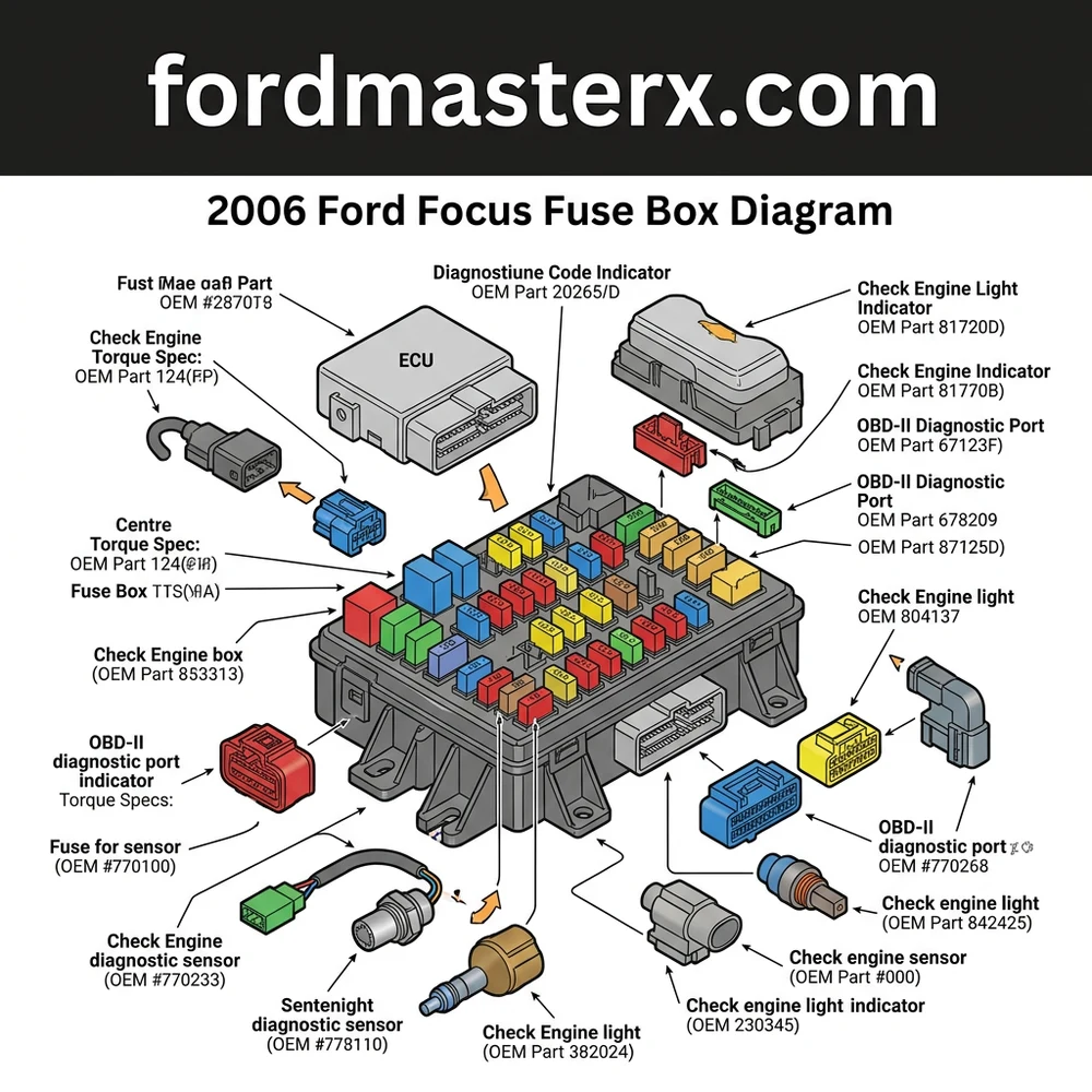
Locating the 2006 Ford Focus Fuse Box Diagram Panels

The 2006 Ford Focus platform divides its electrical architecture into two distinct zones. The Battery Junction Box (BJB) acts as the high-amperage hub, situated in the engine compartment, while the Central Junction Box (CJB) manages low-current interior components. Locating these is the first step in troubleshooting any circuit-related fault.


Engine Compartment Battery Junction Box Placement

The primary power center is located in the engine bay on the driver’s side, positioned near the air cleaner assembly. This unit houses the high-capacity fuses and relays for the cooling fan, starter solenoid, and fuel pump. When inspecting this box, you must verify that the weather seal remains intact; moisture ingress here frequently leads to terminal corrosion. Before opening, ensure the ignition is in the OFF position to prevent accidental shorting of the bus bars. Always refer to the underside of the plastic cover for the specific 2006 Ford Focus fuse box diagram pertinent to your engine trim, as layout variations exist between the Zetec and Duratec engine blocks.
Passenger Compartment Central Junction Box Access


The secondary fuse panel is located behind the glove compartment. To access it, you must depress the side retaining tabs, allowing the glove box to drop fully. This panel is the focal point for the ECU power supply, instrument cluster lighting, and OBD-II port activation. Because this panel is tucked away, technicians often overlook it during initial troubleshooting. However, if your scanner fails to communicate with the OBD-II port, the primary point of failure is often a blown fuse within this interior bank. Always utilize a high-quality non-marring trim tool when removing the panel cover to prevent damage to the dashboard plastics.
Common 2006 Ford Focus Fuse Box Diagram Symptoms and Issues


Faulty electrical flow often manifests through symptoms that may seem unrelated to the fuse box. For instance, a failing fuel pump relay can mimic symptoms of an internal mechanical oil pressure issue or a restricted fuel filter. The following table identifies how specific electrical failures map back to the fuse box diagram.
| Symptom | Potential Circuit Fault | Diagnostic Action |
|---|---|---|
| Engine Crank, No Start | Fuel Pump Relay / ECU Power | Verify continuity of the fuel pump circuit. |
| OBD-II Link Error | Cigarette Lighter / Accessory Fuse | Check the 20A interior fuse for power loss. |
| Cooling Fan Inactive | High-Speed Fan Relay | Check BJB relay contact corrosion. |
| Check Engine Light On | ECU Logic/Sensor Voltage | Scan for diagnostic code after fuse check. |
When investigating these symptoms, you must differentiate between a single blown component and a systemic issue. If a fuse blows immediately upon replacement, you are likely dealing with a short-to-ground in the wiring harness rather than a failing relay. Inspecting the wire insulation for signs of friction, especially near the timing chain cover or transmission housing, is a critical part of the process.
Never replace a fuse with one of a higher amperage rating. Doing so can cause terminal melting or wiring harness combustion before the fuse triggers, potentially causing permanent damage to the ECU or surrounding sensitive electronics.
Diagnosis Steps for 2006 Ford Focus Electrical Circuits
Logical diagnosis requires a structured approach to avoid unnecessary component replacement. If your vehicle displays a diagnostic code related to sensor performance, do not assume a mechanical failure. Electrical fluctuations from a poor ground or weak fuse connection often trigger false positives in the ECU.
1. Code Retrieval: Start by connecting your scan tool to the OBD-II port. If the scan tool does not power on, verify the fuse in the interior junction box corresponding to the accessory outlet. Once active, record every diagnostic code presented.
2. Visual Inspection: Open the fuse boxes and examine the elements for dark, melted, or broken filaments. Even if the fuse appears intact, use a digital multimeter (DMM) to test for continuity across the top test points of the fuse. This confirms if the internal connection is actually closed.
3. Voltage Drop Testing: For circuits involving heavy draw components like the cooling fan or starter, perform a voltage drop test. A healthy circuit should show less than 0.5V drop under load. Significant drops suggest high resistance, often caused by corroded relay pins or loose terminals within the 2006 Ford Focus fuse box diagram blocks.


4. Ground Point Verification: Many electrical issues stem from common chassis ground points rather than the fuses themselves. Ensure the grounding straps near the battery and the engine block are clean and tightened to the proper torque spec. Poor grounds often cause erratic coolant flow readings or false oil pressure warnings as the sensor signals become noisy due to floating voltage.
5. Relay Swapping: If a specific system (like the AC compressor) fails to activate, swap the suspect relay with an identical one from a non-critical circuit (such as the horn). If the symptom moves, you have confirmed a faulty relay.
2006 Ford Focus Fuse Box Diagram Reference Specifications


Maintaining the integrity of the vehicle electrical system requires using the correct amperage and relay types. The following table provides the technical reference points for standard circuits identified in the 2006 Ford Focus fuse box diagram.


| System | Fuse Type/Amps | Operating Voltage |
|---|---|---|
| ECU/PCM | 15A (Micro) | 12.6V |
| Fuel Pump | 20A (Mini) | 12.6V |
| Cooling Fans | 40A (Maxi) | 12.6V |
| Ignition Switch | 30A (Maxi) | 12.6V |
Ensure all battery connections are clean and tightened to 12 Nm (8.8 lb-ft). Proper torque on ground connections is essential to prevent intermittent resistance that can trigger false oil pressure sensor warnings on the instrument cluster.
When evaluating coolant flow or oil pressure sensor data, remember that these sensors rely on consistent 5V reference signals provided by the ECU. If the fuse box shows signs of heat damage, the voltage regulation provided to these sensors may become unstable, resulting in erratic telemetry data. Always use the diagram to verify that no high-amperage components are sharing a ground path with these low-voltage sensors.
2006 Ford Focus Fuse Box Diagram Questions Answered
Can a blown fuse cause my car to fail the emissions test?
Yes. If the fuse supplying the ECU or the OBD-II diagnostic port is blown, the scanner will be unable to retrieve the I/M readiness monitors, leading to an automatic failure during the emissions certification process.
Why does my fuel pump fuse keep blowing?


Repeated failures indicate either a short circuit in the wiring between the fuse box and the fuel pump, or the fuel pump motor is drawing excessive current due to an internal mechanical failure (e.g., restricted movement). Check the current draw with an ammeter before replacing the fuse again.
Are the interior and engine bay fuse boxes connected?
The two units are connected via a series of heavy-gauge primary power wires. A fault in the main supply cable between the Battery Junction Box and the Central Junction Box can cause a complete loss of interior power while the engine still cranks, as the ignition circuit may be routed differently.
Where can I find the specific torque spec for the fuse box mounting bolts?


Mounting hardware for these boxes typically requires 6–8 Nm. Over-tightening can crack the plastic housing, potentially allowing moisture to reach the contact points and cause oxidation. Always consult the specific service manual for your vehicle’s sub-model, as Ford utilized slight variations throughout the 2006 production year.
For owners performing a timing chain service or cooling system overhaul, remember that electrical continuity through the main harness is often affected by the engine’s movement. Ensure all wiring clips are re-secured to avoid wire chafing against the engine block, which is a common cause of mysterious blown fuses in the 2006 Ford Focus platform.
Step-by-Step Guide to Understanding the 2006 Ford Focus Fuse Box Diagram
Identify – Verify the exact fuse box location and match the diagram legend to your specific trim and engine variant.
Locate – Gain access to the fuse panel by releasing the glove box latch or lifting the engine bay cover.
Reference – Use the diagram to map the suspected circuit to the physical fuse slot and confirm the correct amperage rating.
Connect/Route – Use a multimeter to verify voltage at the test points; probe wire colors specified in the circuit guide to ensure signal continuity.
Verify – Insert a new fuse of the exact same color and rating, then clear any pending diagnostic code via an OBD-II scanner.
Troubleshoot – If the fuse blows again, inspect the wiring harness for shorts or test the connected component for excessive current draw.