
2000 Ford Explorer Fuse Box Diagram: Troubleshooting Guide 2026

The 2000 Ford Explorer features two primary fuse panels: the interior panel located on the driver-side instrument panel end and the Power Distribution Box in the engine bay. Use a 12V test light to check for voltage at fuse test points. Always verify current ratings match your owner’s manual before replacement.
📌 Key Takeaways
- The interior panel houses fuses for the GEM module, while the engine bay box handles high-amperage ECU and fuel pump circuits.
- Always disconnect the negative battery terminal when inspecting primary power distribution blocks to prevent shorting against the chassis.
- Ensure all replacement fuses meet the exact amperage; using a higher rating can cause permanent wiring harness damage.
- A common point of failure is corrosion at the base of the battery junction box, often mimicking ECU electrical failures.
- Consult a professional if the OBD-II port shows no power, as this often indicates a blown powertrain control module circuit.
For professional technicians and advanced DIY enthusiasts maintaining the aging fleet of 2000 Ford Explorer SUVs, mastering the electrical architecture is vital. Whether you are addressing an intermittent check engine light, diagnosing a non-responsive ECU, or tracing a parasitic draw, the 2000 Ford Explorer fuse box diagram serves as the primary roadmap. Ford’s electrical design for this model year utilizes a two-tier distribution system that requires precise identification to avoid common diagnostic pitfalls. Understanding the voltage pathways between the Power Distribution Box under the hood and the interior Central Junction Box is essential for any technician tasked with restoring reliability to these high-mileage machines.
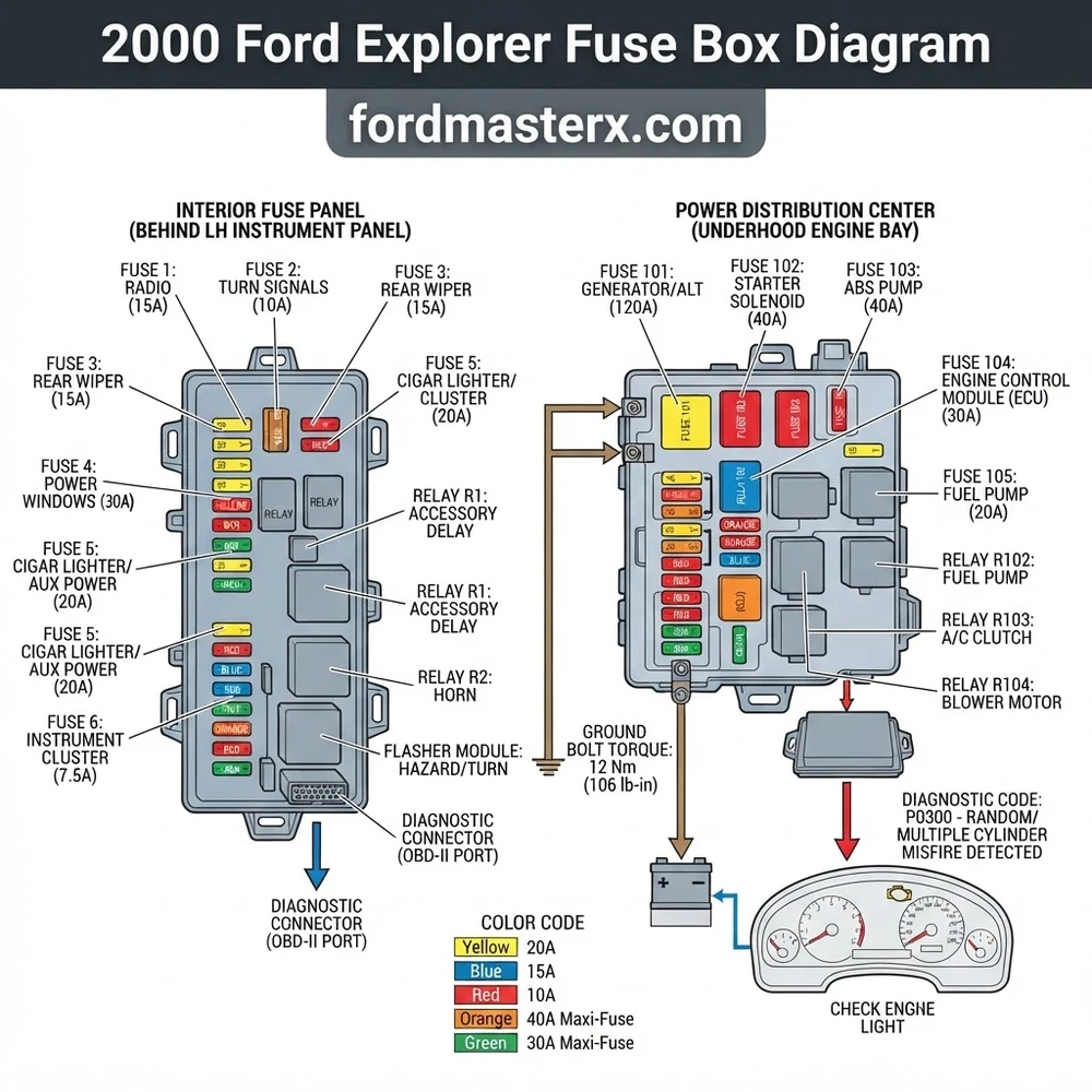
Locating the 2000 Ford Explorer Fuse Box Diagram and Panels

The electrical system of the 2000 Ford Explorer is bifurcated into two distinct geographical zones. To conduct effective diagnostics, technicians must understand that these panels operate under different environmental conditions and handle varying current loads.


The Power Distribution Box (Under-Hood)

The primary power distribution center is located in the engine bay, situated on the driver’s side fender apron near the master cylinder. This unit handles high-amperage current for the ECU, ignition system, fuel pump relay, and cooling fan circuits. Accessing this panel requires the removal of a weather-sealed plastic cover. Given the proximity to the engine block, technicians should inspect the integrity of the harness seals. Corrosion at the base of this box often mimics timing chain or oil pressure sensor failures because poor voltage regulation can cause erratic signals from the Powertrain Control Module (PCM).
The Central Junction Box (Interior)


The second tier of the 2000 Ford Explorer fuse box diagram corresponds to the interior junction box, located behind the driver-side kick panel, beneath the dashboard. This panel controls cabin accessories, such as the instrument cluster, interior lighting, and the OBD-II diagnostic port. When you are attempting to retrieve a diagnostic code and find that your scanner will not link to the ECU, this is the first point of failure. Always check for blown fuses here before concluding that the ECU itself has failed.
Ensure the ignition is in the OFF position before testing continuity on any interior circuits. The OBD-II interface utilizes a constant 12V power supply fed through a dedicated fuse in the interior junction box; if the scanner remains unpowered, verify this circuit first.
2000 Ford Explorer Fuse Box Diagram: Component Identification


Identifying the specific hardware within the 2000 Ford Explorer fuse box diagram is a matter of reading the standardized markings on the underside of the plastic covers. Utilizing the wrong amperage rating can lead to wiring harness damage, while improper relay seating can cause intermittent electrical drops.
| Component Category | Amperage / Range | Primary Function |
|---|---|---|
| Mini Blade Fuse | 5A – 30A | Low-current sensors, interior lamps, ECU triggers |
| Maxi Fuse | 40A – 60A | Main power supply, cooling fan motors, alternator |
| ISO Micro Relay | 12V Constant | Switched ignition, fuel pump, HVAC blower motor |
| Fuse Puller | N/A | Plastic tool typically clipped inside the engine bay cover |
Technicians should note that these fuse boxes are keyed to specific trim levels. A 2000 Ford Explorer with the 5.0L V8 may have different power distribution requirements compared to the 4.0L SOHC V6. When evaluating circuits, refer to the manufacturer’s service manual for the exact torque spec on the main battery cable nut if you are forced to remove the distribution box for terminal inspection.
Common 2000 Ford Explorer Electrical Symptoms and Signs


Electrical gremlins in the 2000 model year often manifest in predictable patterns. By mapping these symptoms back to the 2000 Ford Explorer fuse box diagram, you can save hours of diagnostic time.
- No-Start Condition: Frequently caused by a failed fuel pump relay in the under-hood distribution box. Before condemning the pump, verify voltage at the inertia switch.
- Persistent Check Engine Light: If the light won’t reset even after a repair, inspect the ECU constant power fuse. A blown fuse here wipes PCM memory, resulting in incomplete drive cycle tests.
- Erratic Gauges (Oil Pressure/Temp): These are often ground-side issues. If the gauges jump or read full-scale, verify the ground straps associated with the fuse box chassis mounts.
- Dead OBD-II Port: Almost exclusively related to the power feed circuit in the interior junction box. Check the cigarette lighter fuse as they often share a common power rail.
- Short-to-Ground: Indicated by repeated blowing of a specific fuse. Disconnect the load, then use a multimeter to check for continuity to the chassis.
Never substitute a fuse with a higher amperage rating than specified. Using a 30A fuse in a 15A slot creates a high risk of wiring harness combustion, especially in circuits controlling the ECU or fuel delivery systems.
Troubleshooting Steps for the 2000 Ford Explorer Fuse Box
A systematic approach is required when the 2000 Ford Explorer fuse box diagram indicates a potential failure. Follow these steps to ensure safety and accuracy.
- Visual Inspection: Remove the covers and inspect for signs of thermal damage, such as melted plastic or discolored copper terminals. Even if the fuse is intact, a loose terminal can cause high resistance, leading to voltage drops.
- Test for Battery Voltage: Using a multimeter set to DC volts, probe the test points on top of the blade fuses. If the fuse is good, you should see identical voltage (approx. 12.6V with engine off) on both sides of the fuse.
- Verify Ground Continuity: Using a known good chassis ground, check for resistance between the negative terminal of the battery and the mounting points of the fuse block. Excessive resistance here often leads to false diagnostic codes that look like engine sensor failures.
- Component Isolation: If a specific circuit is popping fuses, isolate the downstream component. For instance, if the fuel pump fuse is blowing, disconnect the pump harness at the tank and see if the fuse holds. If it does, the fault lies in the motor; if not, the fault is in the wiring harness.
- ECU Power Cycle: If you suspect the ECU has locked up, pull the Keep-Alive Memory (KAM) fuse for 15 minutes. This forces a cold reset of the powertrain module, which can clear stuck solenoids or temporary software glitches.
When re-securing the power distribution box after deep diagnostics, ensure the mounting fasteners are torqued to 8-10 Nm to ensure proper ground contact between the metal box base and the fender apron. Over-tightening can strip the threads in the sheet metal.
Finally, always perform a visual check of the timing chain tensioner and coolant flow systems while the hood is open for electrical testing. On high-mileage Ford Explorers, electrical issues often coincide with mechanical wear; neglecting the health of the engine block while focusing solely on the fuse box can result in a vehicle that has power but lacks mechanical integrity.



2000 Ford Explorer Fuse Box Diagram Questions Answered
Why does my OBD-II port show no power?
The OBD-II data link connector on the 2000 Ford Explorer is typically powered through the same circuit that feeds the cigarette lighter. Check the interior junction box for a blown 20A fuse. If the fuse is intact, use a test light at the port to verify that pin 16 is receiving 12V.


Can a bad fuse cause an oil pressure light?


While the oil pressure sensor is a mechanical device, its signal is processed by the instrument cluster, which receives power from the interior fuse panel. If the cluster is receiving unstable voltage due to a corroded fuse terminal, it can cause the gauge to fluctuate or trigger the warning lamp falsely.
How do I identify which relay is for the fuel pump?
Refer to the embossed map on the interior of your power distribution box cover. The fuel pump relay is generally labeled “FP” or “FUEL PUMP.” If you are unsure, you can perform a resistance check on the relay coil; a failed internal solenoid will usually show an open circuit (OL) on a multimeter.
Does a blown ECU fuse require a computer reset?


Replacing a blown fuse for the ECU/PCM circuit will restore power, but the computer may need to relearn its idle strategy. After replacing the fuse, allow the engine to reach operating temperature at idle for 10 minutes to allow the PCM to adjust air-fuel ratios and timing maps appropriately.


Step-by-Step Guide to Understanding the 2000 Ford Explorer Fuse Box Diagram
Identify – Locate the interior and under-hood fuse box covers and match them against the diagram.
Locate – Find the specific fuse number related to your malfunction, such as the fuel pump or ECU circuit.
Reference – Use a multimeter to verify voltage on both test points of the fuse while the ignition is in the ON position.
Connect/Route – If a fuse is blown, inspect the wiring harness for signs of wear before installing a replacement fuse of the correct rating.
Verify – Clear any pending diagnostic code with an OBD-II scanner and road-test the vehicle to confirm the electrical fault is resolved.
Troubleshoot – If the fuse blows again immediately, inspect the ground connections and perform a visual check of the wiring harness for insulation failure.