
1992 Ford Ranger Fuse Box Diagram: Troubleshooting Guide 2026

The 1992 Ford Ranger fuse panel is located behind the driver-side kick panel. It contains ATO-style fuses ranging from 5A to 30A. Pinouts control the ECU power relay and fuel pump circuit. Always verify the diagram against your specific engine trim, as the 2.3L, 3.0L, and 4.0L configurations vary significantly.
📌 Key Takeaways
- Use a 12V test light or digital multimeter to check for voltage on both fuse test points before assuming a component failure.
- The fuse block identification labels are molded into the plastic cover; cross-reference these with the OEM owner’s manual.
- When securing cover fasteners, apply a light touch; do not exceed 5-7 inch-pounds of torque to prevent cracking the aged plastic housing.
- Corroded fuse terminals are a leading cause of intermittent electrical issues and false diagnostic codes.
- If multiple circuits fail simultaneously, check the fusible links near the starter solenoid before performing deep electrical diagnostic work.
Maintaining the electrical integrity of a vintage truck requires precise documentation, especially when dealing with the nuanced circuitry of the 1992 Ford Ranger. As a transitional year for Ford’s compact truck platform, the electrical architecture bridges the gap between mechanical simplicity and the early introduction of computerized engine management. Whether you are addressing an erratic check engine light, diagnosing a non-responsive ECU, or troubleshooting a total power loss, understanding the location and function of every circuit is critical. This guide breaks down the 1992 Ford Ranger fuse box diagram to provide a reliable reference for your diagnostic efforts, ensuring you can identify, test, and replace components with OEM-level accuracy.
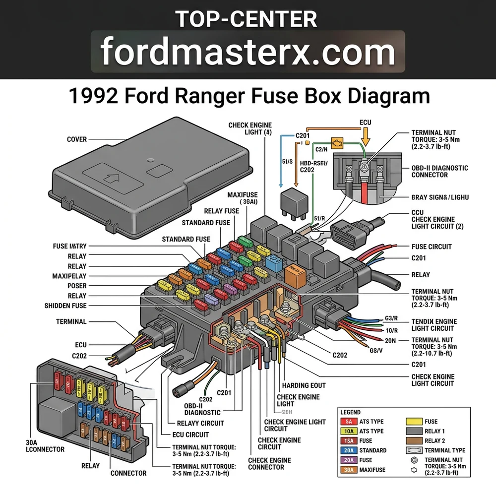
1992 Ford Ranger Fuse Box Diagram and Component Identification
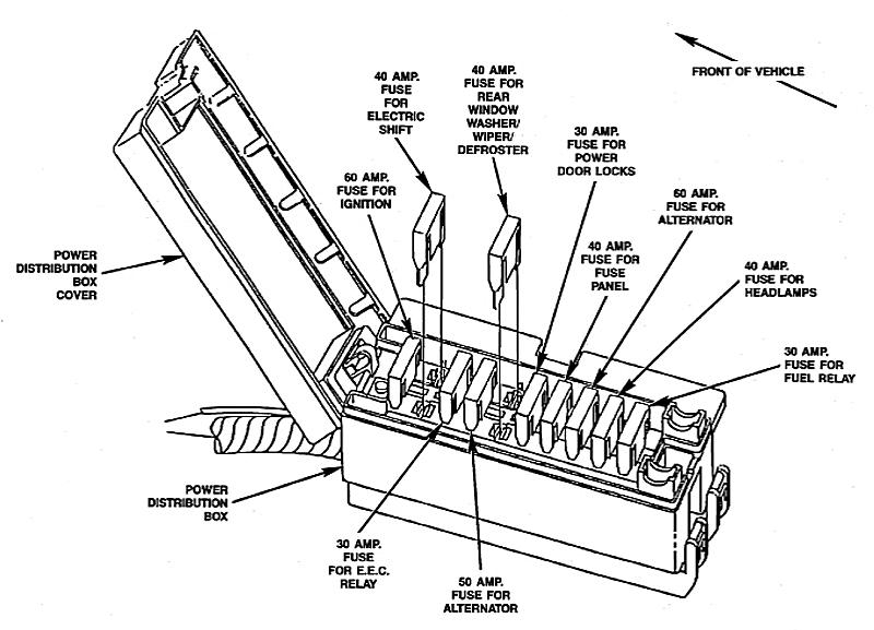
The electrical distribution system in the 1992 Ford Ranger utilizes two primary hubs to manage current flow: the internal instrument panel fuse block and the engine compartment power distribution box. Identifying which circuit controls which load is the first step in successful troubleshooting. The instrument panel fuse block is located typically under the driver-side dashboard, accessible by removing the plastic cover panel. Conversely, the engine compartment power distribution box is located near the battery, housing high-amperage fuses and relays responsible for major systems like the ECU and cooling fan.


| Circuit Designation | Amperage | Protected System |
|---|---|---|
| Fuse 1 | 15A | Instrument Cluster/Gauges |
| Fuse 4 | 20A | Fuel Pump/ECU Power |
| Fuse 7 | 10A | Turn Signals/Flashers |
| Fuse 12 | 25A | Blower Motor/HVAC |
| Fusible Link A | 60A | Main Ignition Feed |
When inspecting these boxes, rely on blade-style fuses that allow for visual inspection of the internal metal link. If the bridge is broken, the circuit is open. Be cautious with older vehicles; sometimes a fuse may appear intact but have high resistance due to corrosion on the terminal blades. Always replace fuses with the exact amperage rating specified in the owner’s manual. Substituting a 10A fuse for a 20A circuit will cause immediate failure, while installing a higher-rated fuse creates a significant fire hazard by allowing the wire to carry more current than it was engineered to handle, potentially melting the insulation and causing a short.
In addition to standard fuses, the power distribution box utilizes fusible links. These are lengths of smaller-gauge wire designed to melt and open the circuit if an extreme current spike occurs. Unlike blade fuses, these are not easily replaceable and often signify a deeper short to ground. If a fusible link is blown, do not attempt to bypass it with standard wire. You must repair the underlying fault first, as the link acted as a critical safety barrier for your vehicle’s harness.
Note that the 1992 model year predates universal OBD-II standardization. While it features an electronic engine management system, it utilizes the older EEC-IV diagnostic port. Do not attempt to use modern OBD-II scanners without a specific adapter, or you will fail to retrieve any diagnostic codes.
Common 1992 Ford Ranger Fuse Box Diagram Issues and Symptoms



When troubleshooting electrical issues, differentiating between a simple fuse failure and a component-level malfunction is vital. A blown fuse usually points to a downstream short circuit. If you replace a fuse and it blows immediately upon turning the ignition to the “Run” position, the fault is “hard” and likely involves a wire that has chafed against the chassis or a component (such as a solenoid) that has internally shorted.
Common symptoms of fuse-related problems include dead instrument clusters, failure of the fuel pump to prime, or a non-functioning HVAC system. If you notice your oil pressure gauge dropping or fluctuating alongside flickering lights, check the ground connections in the engine bay before blaming the fuse block. Poor grounding is a frequent “ghost” issue in 1992 Rangers, often creating resistance that mimics an open circuit.
Never use a screwdriver or pliers to bridge a fuse terminal. This can cause arcing that welds the metal terminals, permanently damaging the fuse block housing and creating an uncontrolled fire risk.
Relays are another common failure point. Unlike a fuse that protects against current spikes, a relay acts as a remote switch. If a relay clicks but the circuit fails, the contacts inside the relay are likely pitted or burned. Conversely, if there is no audible click, the control side of the relay circuit—often controlled by the ECU—might be failing. Always verify the relay by swapping it with an identical part from a non-critical circuit (like the horn relay) to rule out mechanical failure before tracing wires.
Finally, inspect the terminals inside the power distribution box. Over time, heat cycles can cause the plastic housing to expand, resulting in loose terminal retention. A loose connection creates high resistance, which leads to heat generation and eventual melting of the fuse box base. If you see signs of heat discoloration on the plastic near a fuse, the entire terminal block may require replacement.
Step-by-Step Diagnosis for 1992 Ford Ranger Electrical Faults


To diagnose faults involving the ECU, fuel pump, or lighting, follow a systematic approach. Start by verifying the state of the circuit using a digital multimeter set to DC volts or continuity.


1. Reference the Owner’s Manual: Before touching any wiring, compare your findings against the official manufacturer’s schematic for the 1992 Ford Ranger. Verify the specific circuit’s current load and wire gauge requirements.
2. Test for Battery Voltage at the Fuse: With the ignition switch in the “On” position, use your multimeter to check for 12V at the top of the fuse. If there is no voltage on either side of the fuse, the problem lies upstream, likely within the ignition switch or the main power supply from the battery.
3. Verify Continuity to Ground: If you suspect a short circuit, disconnect the negative battery terminal. Set your multimeter to “Ohms” (Ω) and test the load side of the fuse terminal to a known good chassis ground. A reading of 0 Ohms indicates a direct short to the body of the vehicle. If the reading is high, the circuit is likely intact.
4. Inspect the ECU/EEC-IV Diagnostic Port: If you are chasing a check engine light or performance issues, utilize a jumper wire or an EEC-IV compatible code reader on the diagnostic port. The flash codes retrieved through this port provide essential data regarding timing, fuel mixture, and sensor health that aren’t visible through physical fuse inspection.
5. Analyze Physical Connections: Ensure all major grounding points—specifically the engine-to-chassis strap—are clean and tight. Corrosion on these straps increases internal resistance, forcing the electrical system to draw more current through secondary paths, which can trigger periodic fuse failures.
6. Check Component Specs: If an electrical load is consistently blowing its fuse, verify the component’s draw. For instance, if the fuel pump is failing, it may be drawing excessive amperage as it struggles to overcome internal mechanical drag. Before replacing the fuse, confirm the current draw does not exceed 80% of the circuit’s capacity.


When replacing engine-related sensors or timing chain tensioners that may share electrical grounds, always adhere to OEM torque specs. Over-torquing a sensor mount can damage internal windings, while under-torquing leads to vibration-induced grounding failures. Check the service manual for the exact torque spec (measured in inch-pounds or foot-pounds) for your specific engine displacement.
When diagnosing coolant flow sensors or oil pressure switches, keep in mind that these components often complete a circuit to ground. A failing sensor may ground out intermittently, potentially causing the gauge to spike or triggering a warning light that leads you to believe the issue is electrical. If you have confirmed the fuse is good and there is voltage at the sensor connector, but the component remains unresponsive, the fault is likely in the sensor’s internal resistance or the wiring harness leading back to the gauge cluster.
Consistency is key during the diagnostic process. Never rely on visual inspection alone; even a “good” looking fuse can be internally fractured. Use a test light or a multimeter to confirm voltage passes through the fuse while the circuit is under load. By following these steps, you can isolate complex electrical issues in your 1992 Ford Ranger without replacing expensive, non-defective parts.
1992 Ford Ranger Fuse Box Diagram Questions Answered
Why does my check engine light remain on even after I replace a blown fuse?
A blown fuse typically interrupts power to the ECU or a sensor, which triggers a code, but replacing the fuse does not automatically clear the existing error from the computer’s memory. You must perform a “hard reset” of the EEC-IV system or use a diagnostic scanner to clear the diagnostic code after the physical fault is repaired.


Can I upgrade to a higher-amperage fuse to stop it from blowing?
Absolutely not. The fuse is sized to protect the weakest link in the wiring harness. Replacing a 15A fuse with a 20A or 30A unit risks melting the wire insulation, which can lead to an electrical fire. If a fuse continues to blow, you have a short circuit that must be repaired.
Where is the main power distribution box located?
On the 1992 Ford Ranger, the power distribution box is located in the engine bay, usually mounted on the driver-side fender well or near the firewall. This box contains the high-amperage fuses and relays for the ignition, fuel pump, and primary ECU power feeds.
How do I diagnose an oil pressure gauge that reads zero?
First, check the dedicated fuse for the instrument cluster in the interior fuse block. If the fuse is intact, locate the oil pressure sending unit on the engine block. Disconnect the sensor and ground the wire; if the gauge needle moves to “High,” the wiring and gauge are functional, and the sensor itself has likely failed.
What is the purpose of the EEC-IV diagnostic port?
The EEC-IV port is the precursor to the modern OBD-II system. It provides a means to retrieve stored fault codes from the engine management computer. If your engine has poor fuel economy or erratic idling, testing this port is the most efficient way to pinpoint if the issue is a failed sensor, a vacuum leak, or a timing chain issue that is affecting the ECU’s ability to maintain proper idle and air-fuel ratios.


