
Ford Ranger AC System Diagram: 2026 Component Breakdown

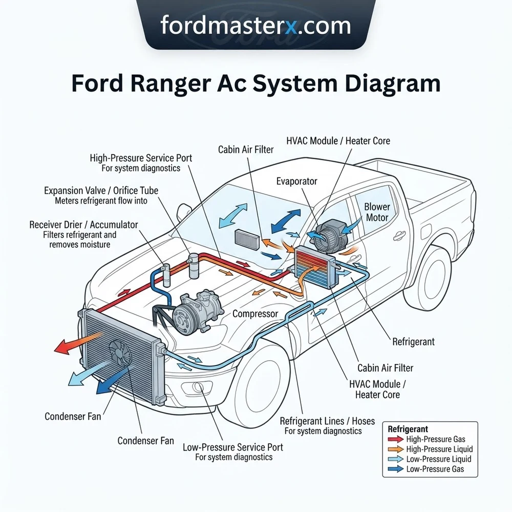
The Ford Ranger AC system relies on a high-pressure loop circulating R-134a or R-1234yf refrigerant. The compressor, driven by the serpentine belt, pushes gas through the condenser. The refrigerant then passes through the orifice tube to the evaporator, where the blower motor forces air across cooling fins to deliver cold air.
📌 Key Takeaways
- Refrigerant capacity varies by model year; refer to the under-hood sticker for exact 1.2–1.8 lbs specifications.
- The clutch cycling switch is the primary electronic sensor for monitoring low-side pressure.
- Always evacuate the system using a vacuum pump to 29.9 in-Hg before introducing new refrigerant.
- Compressor seizure is frequently caused by a restriction in the orifice tube or low lubricant levels.
- Seek professional HVAC recovery if the system shows signs of heavy oil contamination or metallic debris.
Achieving optimal cabin comfort in a Ford Ranger requires a functional grasp of the heating, ventilation, and air conditioning (HVAC) loop. Whether you are servicing a classic 1998–2011 platform or the modern T6 architecture, the Ford Ranger AC system diagram serves as the definitive roadmap for diagnosing thermal performance issues. This guide dissects the intricate interplay between the mechanical refrigerant cycle and the electrical logic managed by the Powertrain Control Module (PCM). By understanding how components like the compressor, condenser, and evaporator interact within the air handler, technicians can isolate faults ranging from low-pressure switch dropouts to seized clutch coils, ensuring the HVAC system operates within strict manufacturer tolerances.
Understanding the Ford Ranger AC System Diagram Components


To effectively navigate the Ford Ranger AC system diagram, you must treat the assembly as two distinct loops: the refrigerant (high-pressure/low-pressure) loop and the electrical control circuit. The refrigerant loop relies on physical phase changes—liquid to gas and back—to absorb heat from the cabin and reject it into the atmosphere. The electrical circuit, meanwhile, governs the compressor engagement and blower speed via signals from the HVAC control module.


The following table delineates the primary hardware components identified in the OEM schematics.
| Component | Function in Refrigerant Loop | Technical Characteristic |
|---|---|---|
| Compressor | Mechanical pump; pressurizes vaporized refrigerant. | Variable/Fixed displacement via clutch coil. |
| Condenser | Heat exchanger; releases heat to ambient air. | Located front-most behind grille. |
| Evaporator | Heat exchanger; absorbs cabin heat into refrigerant. | Deeply buried in the air handler assembly. |
| Orifice Tube | Restricts flow; initiates pressure drop/expansion. | Commonly clogged; check during system open. |
| Blower Motor | Forced convection; pulls air through return duct. | PWM controlled in late-model units. |
The Role of the Heat Exchanger and Air Handler

The air handler is the centralized housing that manages the distribution of conditioned air. Within this assembly, the heat exchanger (evaporator core) acts as the site of thermodynamic exchange. When the blower motor pulls air from the return duct, the air passes over the fins of the evaporator. According to Ford engineering standards, the expansion of the refrigerant—triggered as it passes through the orifice tube or thermal expansion valve—causes a rapid drop in temperature. If the air handler’s blend doors are blocked or malfunctioning, air will bypass the evaporator, leading to an immediate loss of cooling capacity even if the refrigerant pressure remains within specifications. Always verify that the vacuum or electric actuators are achieving full travel when moving from “Max A/C” to “Heat” positions.
Mechanical Refrigerant Pathing


The refrigerant cycle begins at the compressor inlet, where low-pressure gas is drawn in. The compressor discharge line then pushes high-pressure, high-temperature gas to the condenser. As ambient air flows over the condenser fins, the refrigerant condenses into a high-pressure liquid. This liquid flows through the liquid line—monitored by the high-pressure cutout switch—toward the orifice tube. After expansion, the low-pressure cold liquid enters the evaporator. Finally, the suction line carries the low-pressure vapor back to the compressor to restart the cycle. Refer to your specific year’s technical manual for the exact refrigerant charge in ounces, as deviation from this specification will compromise compressor longevity.
For Ranger models manufactured after 2012, ensure you are using R-1234yf refrigerant equipment. Early models utilizing R-134a require specialized couplers to prevent cross-contamination, which can cause internal compressor oil degradation.
How to Read the Ford Ranger AC System Diagram for Diagnosis


Effective diagnostic work requires a systematic trace of the control signals. When the AC is toggled on, the circuit must complete a path from the HVAC module through the PCM to the compressor clutch relay. If this loop is broken at any point, the compressor will not engage.
1. Verify Power at the Clutch Relay: Use a multimeter to verify 12V+ at the control side of the AC compressor clutch relay. If voltage is absent, trace back to the AC pressure switch. A common failure point is the low-pressure cycling switch, which prevents compressor engagement if the refrigerant charge is below the minimum threshold (typically 25-30 psi).
2. Inspect the PCM Signal: On modern Rangers, the PCM monitors the high-pressure transducer. If the pressure readings are irrational—due to a failing sensor or internal condenser blockage—the PCM will inhibit the ground signal to the compressor clutch relay. Refer to your OBD-II scanner’s live data stream to compare the PCM’s perceived pressure against a mechanical gauge manifold.
3. Analyze the Blower Motor Circuit: If the blower motor is inoperative, check the resistor pack or the blower motor speed controller. In the diagram, note the wiring harness pinout; a high-resistance ground at the connector is a frequent cause of intermittent blower speed, often mistaken for a failed motor.
4. Evaluate the Blend Door Logic: If the system is cold but the air delivered at the vents is warm, do not assume a refrigerant leak. Use the diagram to identify the blend door actuator circuit. Apply 12V to the motor leads to verify physical rotation; if the motor hums but the output remains unchanged, the internal door coupler has likely stripped.
5. Check the Return Duct and Cabin Filter: Ensure that the return duct is not obstructed by debris. A restricted filter inhibits the volume of air passing through the evaporator, which can lead to ice buildup on the core, further restricting airflow and causing the system to blow warm air despite functional refrigeration.
Standard compressor clutch air gap for Ford Ranger (1998-2011) should measure between 0.014″ and 0.030″. Use a feeler gauge; if the gap exceeds 0.035″, the clutch may fail to engage when hot due to increased resistance.
Troubleshooting Common Ford Ranger AC System Diagram Failures


Utilizing the schematic allows for rapid isolation of system faults. Below are the most frequent failure modes encountered when servicing these vehicles.


Compressor Clutch Inactivity: If the clutch fails to engage, start by jumping the low-pressure switch connector. If the clutch snaps in, the system is low on refrigerant. If it remains off, test the relay coil for continuity and ensure the ground wire (usually black/yellow) has a solid chassis connection.
Warm Air Despite Low-Side Pressure: If your low-side gauge reads within the proper range (30-40 psi at 80°F ambient) but vent temperatures remain high, the culprit is likely the blend door actuator. The diagram identifies the actuator behind the center console. Use an oscilloscope to check the PWM signal from the climate control module; if the signal is steady but the motor does not move, replace the actuator.
Blower Motor Intermittency: A common Ford Ranger issue is the blower motor resistor overheating. The diagram shows this resistor in series with the motor. If the fan only works on “High,” the thermal fuse inside the resistor block has tripped. Replace both the resistor and the connector pigtail, as excessive heat often melts the plastic housing.
High-Side Pressure Spikes: If the high-side pressure exceeds 300 psi during operation, the condenser may be obstructed, or the fan is not providing enough airflow. Check the radiator cooling fan clutch (if mechanical) or the electric fan motor relay. The PCM will trigger a high-pressure cutout to prevent system rupture; if this occurs, the compressor will cycle off rapidly.
* Evaporator Freezing: If the system works well for 15 minutes and then slowly loses airflow, the evaporator is likely icing over. This is often caused by a failing evaporator temperature sensor, which tells the PCM to cycle the compressor off when the core temperature approaches 32°F. Consult the diagram to trace the sensor signal back to the HVAC module.
Always wear safety goggles and gloves when working with refrigerant. High-pressure leaks can cause severe frostbite. Never discharge refrigerant into the atmosphere; use an EPA-certified recovery machine.
Ford Ranger AC System Diagram Questions Answered
Where is the AC low-pressure switch located on the Ford Ranger?


The low-pressure switch is typically mounted on the accumulator (drier) canister, which is found in the engine bay on the passenger side near the firewall. It monitors the suction side of the refrigerant loop. If the refrigerant level drops, this switch opens the circuit, preventing the compressor from running without adequate lubrication.
Can I bypass the pressure switch to test the compressor?


You can temporarily bridge the switch terminals with a fused jumper wire to confirm the compressor clutch is functional. However, do not operate the system this way for more than a few seconds. If the compressor engages, your fault is likely a low refrigerant charge or a failed pressure switch, not the compressor itself.


What causes the AC to blow air only from the defrost vents?


This is a classic symptom of a vacuum leak or a failed mode door actuator. In older Ford Rangers, the HVAC system uses vacuum lines to move the doors between “Vent,” “Floor,” and “Defrost.” If you lose vacuum pressure, the system defaults to “Defrost” as a safety measure. Inspect the vacuum lines near the battery tray for dry-rot or cracking.
How often should I replace the AC receiver/drier?
You should replace the receiver/drier (or accumulator) whenever the refrigerant system is opened for major repairs, such as replacing the compressor or evaporator. The desiccant bag inside the unit absorbs moisture; once exposed to ambient air for more than a few minutes, its capacity is exhausted, leading to acid formation and potential system-wide corrosion.
Does the Ford Ranger AC system diagram change across model years?
Yes. The 1998–2011 Rangers utilize a simpler analog circuit with vacuum-controlled doors. The 2019+ T6 platform utilizes a complex digital communication network (CAN bus) where the HVAC module sends data to the Body Control Module (BCM) and PCM. Always verify your VIN-specific schematic before attempting electrical repairs, as wire colors and module logic differ significantly.


Step-by-Step Guide to Understanding the Ford Ranger Ac System Diagram
Identify – Locate the compressor clutch connector and the low-side service port using the diagram layout.
Locate – Find the blower motor housing under the passenger side dash to assess airflow issues.
Reference – Use the diagram to trace the specific high-pressure hose routing from the condenser to the evaporator inlet.
Connect/Route – Secure all refrigerant lines ensuring no kinks exist, and plug in the clutch cycling switch connector.
Verify – Perform a vacuum test followed by a system charge, then measure temperature at the center vents.
Troubleshoot – If the clutch fails to engage, use a multimeter to check for 12V at the compressor plug per the wiring guide.