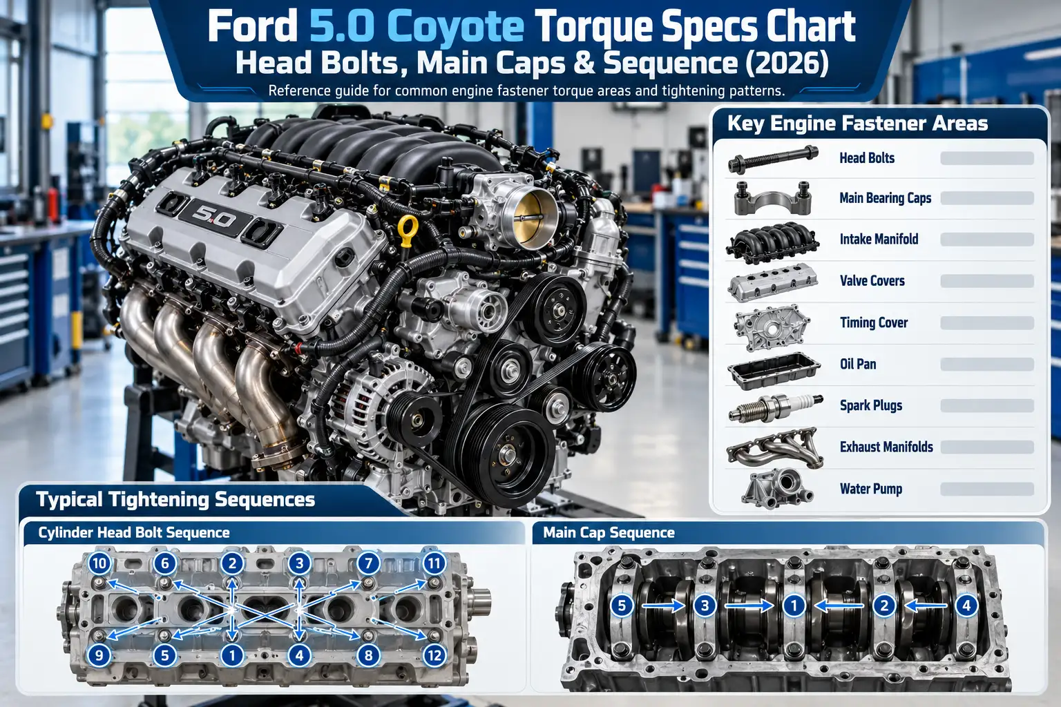
Ford 5.0 Coyote Torque Specs Chart: Head Bolts, Main Caps & Sequence (2026)

Ford 5.0 Coyote torque specs are not one universal set of bolt-tightening numbers. The correct specification depends on the engine application, fastener, hardware revision, and whether Ford calls for additional rotation after an initial torque setting.
For example, a documented 2011 F-150 cylinder head procedure differs from Ford Performance’s later Mustang head-gasket kit instructions. This guide separates production-engine specifications from those for the Gen 3 Aluminator crate engine.
The tables give verified numbers where the source identifies the exact application; they are not permission to transfer those numbers to every 5.0L Coyote.
FordMasterX · Application-specific torque data
5.0L Coyote Torque Quick Reference
Match the engine and hardware before using any value. Tightening angles are additional rotations, not final torque readings.
01 · Production F-150 head bolts
2011 Ford F-150 5.0L Cylinder Head
Stock production engine · New torque-to-yield bolts
Use new bolts on both heads. Follow the correct RH/LH factory bolt order; these values are for the 2011 F-150 5.0L procedure.
02 · Ford Performance head kit
2018–2025 Mustang 5.0L Head Gasket Kit
Ford Performance M-6067-M5018 · Supplied KR3Z-6065-A head bolts
Follow the kit’s numbered bolt order. Each angle pass is 90 ± 5°. This kit procedure is not a universal Coyote head-bolt specification.
03 · Component reference
2018–2022 Gen 3 Aluminator NA Crate Engine
Ford Performance M-6007-A50NAB · Crate-engine hardware only
| Component | Tightening spec |
|---|---|
| Camshaft bearing cap bolts | 6 Nm + 45° |
| VCT phaser assembly bolts | 15 Nm + 90° |
| Primary timing-chain tensioner | 10 Nm + 25° |
| Spark plugs | 15 Nm |
| Standard cam cover bolts | 15 Nm |
| Oil pan bolts | 10 Nm + 45° |
Confirm model year, engine application, hardware, fastener reuse rules, and the complete Ford tightening sequence. Do not apply crate-engine values to an unidentified production F-150 or Mustang.
Technical references: 2011 F-150 5.0L service procedure (Operation CHARM); Ford Performance M-6067-M5018 and M-6007-A50NAB. The complete manufacturer procedures control.
Ford 5.0 Coyote Torque Specs Quick Reference Chart
Recommended Best Deal Products

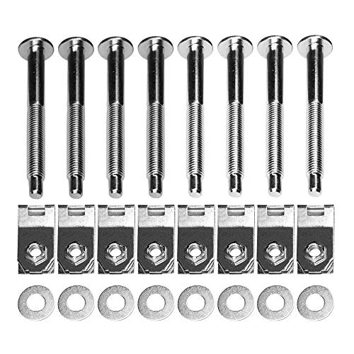
Start by matching your engine to the application column. Nm means newton-meters, lb-ft means pound-feet, and lb-in means pound-inches. A value followed by + 90° means to tighten to the stated torque, then rotate the fastener an additional 90 degrees as directed by the procedure.
| Component | Verified application | Tightening specification |
|---|---|---|
| Cylinder head bolts | 2011 F-150 5.0L | 25 Nm, 40 Nm, +90°, +90° |
| Vertical main cap bolts | 2011 F-150 5.0L | 20 Nm; outer 40 Nm, inner 65 Nm; all +90° |
| Main cap side bolts | 2011 F-150 5.0L | 10 Nm, 30 Nm, +60° |
| Connecting rod cap bolts | 2011 F-150 5.0L, stock procedure | 20 Nm, 38 Nm, +105°; new bolts |
| Cylinder head bolts | 2018–2025 Mustang, Ford Performance M-6067-M5018 kit | 30 ± 5 Nm, 50 ± 5 Nm, three +90° passes |
| Camshaft bearing cap bolts | 2018–2022 Gen 3 Aluminator M-6007-A50NAB | 6 Nm +45° |
| VCT phaser assembly bolts | Same Gen 3 Aluminator | 15 Nm +90° |
| Primary chain tensioner bolts | Same Gen 3 Aluminator | 10 Nm +25° |
| Spark plugs | Same Gen 3 Aluminator | 15 Nm (11 lb-ft) |
| Cam cover bolts | Same Gen 3 Aluminator, standard positions | 15 Nm (11 lb-ft) |
| Oil pan bolts | Same Gen 3 Aluminator | 10 Nm +45° |
| Exhaust manifold nuts | Same Gen 3 Aluminator | 33 Nm (24 lb-ft) |
Read the application column first. The 2011 values come from the reproduced Ford engine-assembly procedure for that truck. The Aluminator values come from the Ford Performance Gen 3 Aluminator installation sheet. A production 2018 F-150 is not automatically covered by the Gen 3 Aluminator column.
For wheel, drain-plug, and other whole-truck fasteners, use the separate Ford F-150 torque specifications chart. Those jobs are deliberately excluded from this engine-assembly guide.
Which 5.0 Coyote Generation Is in Your Ford
The Coyote name spans several related engines, but Mustang generations should not be used as a substitute for an F-150 engine identification.
| Mustang GT application | Common engine generation | Why identification matters |
|---|---|---|
| 2011–2014 | Gen 1 | Early production fasteners and procedures |
| 2015–2017 | Gen 2 | Revised head hardware and gaskets |
| 2018–2023 | Gen 3 | Revised engine architecture and direct injection |
| 2024–2026 | Gen 4 | Later hardware and dual-throttle-body configuration |
The F-150 also received updates to its 5.0L V8 over this period, but its changes do not always match Mustang changes by model year. Confirm the engine installed in your truck, not just the badge on the tailgate.
Ford Performance identifies 11 mm torque-to-yield head bolts in its 2015–2017 Mustang Coyote head-changing kit. Later Ford Performance head kits specify a different 12 mm fastener arrangement. That is a hardware difference, not a reason to assume that all earlier or later engines use the same tightening stages.
For differences in the engine itself, the Gen 3 Coyote engine specifications provide useful background. Once the generation is established, select the matching repair procedure.
How to Torque Ford Coyote Cylinder Head Bolts
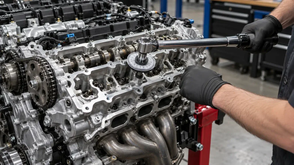
Cylinder head tightening is a staged procedure. The bolts must be installed in the prescribed order, and torque-angle stages must be completed using an angle gauge or an appropriate electronic torque tool. The numerical stages below apply only to the applications named.
2011 F-150 Production Engine
The 2011 F-150 5.0L factory engine-assembly instructions, reproduced in the Ford service manual assembly procedure, call for new cylinder head bolts. On each head, follow the illustrated bolt order and complete four stages:
- Tighten to 25 Nm (18 lb-ft).
- Tighten to 40 Nm (30 lb-ft).
- Rotate an additional 90°.
- Rotate an additional 90°.
These are the documented 2011 truck stages, not a blanket specification for every Gen 1 Mustang, later F-150, or aftermarket head bolt.
2018–2025 Mustang Head-Gasket Kit
The Ford Performance M-6067-M5018 instruction sheet describes a specific Mustang head-gasket and head-bolt kit using KR3Z-6065-A bolts. It calls for the numbered sequence in its drawing and these stages:
- Tighten all fasteners to 30 ± 5 Nm.
- Tighten all fasteners to 50 ± 5 Nm.
- Rotate each fastener 90 ± 5° in sequence.
- Repeat the 90 ± 5° rotation for a second pass.
- Repeat the 90 ± 5° rotation for a third pass.
The sheet identifies its application as 2018–2025 Mustang 5.0L, even though some related Ford Performance product listings show broader kit compatibility. For a 2026 vehicle, confirm the latest applicable instruction before using the kit procedure.
Gen 3 Aluminator Crate Engine
Ford’s Gen 3 Aluminator NA installation document instead specifies 25 Nm, followed by 75 Nm, then a different individual-bolt loosening and retightening procedure ending at 50 Nm plus 235–245°. It uses the sequence illustrated in that document.
This is a clear example of why a single internet chart cannot replace the correct fastener instructions. Do not substitute the Aluminator sequence for the M-6067-M5018 kit sequence, or either one for an unidentified stock engine.
How to Torque Coyote Main and Rod Bolts
Main bearing cap bolts and connecting rod bolts secure different components. Both need the exact procedure for the crankshaft, caps, rods, and installed fasteners.
2011 F-150 Main Bearing Caps
For the stock 2011 F-150 5.0L, the reproduced Ford engine-assembly instructions specify the following vertical main bearing cap bolt stages, following the factory numbered order:
- Tighten bolts 1 through 20 to 20 Nm (177 lb-in).
- Tighten bolts 1 through 10 to 40 Nm (30 lb-ft).
- Tighten bolts 11 through 20 to 65 Nm (48 lb-ft).
- Rotate bolts 1 through 20 another 90°.
The cross-mounted side bolts have their own stages: 10 Nm (89 lb-in), 30 Nm (22 lb-ft), then 60°. Do not interchange the numbered vertical-bolt groups or skip the side-bolt procedure.
2011 F-150 Connecting Rod Caps
The same 2011 factory engine-assembly procedure specifies new connecting rod bolts and three stages: 20 Nm (177 lb-in), 38 Nm (28 lb-ft), then 105°. Rod caps must remain with their matched rods and original orientation.
Gen 3 Aluminator Rod Hardware
The 2018–2022 Aluminator M-6007-A50NAB uses Manley forged connecting rods with ARP2000 bolts, not the stock 2011 F-150 rod hardware. Its Ford Performance sheet lists 88 Nm (65 lb-ft) with engine oil and a rod-bolt stretch target of 0.0058–0.0062 inch.
The Aluminator main-cap procedure also uses 20 Nm across the numbered vertical fasteners, 40 Nm on the outer group, 65 Nm on the inner group, and a 90° rotation. Its side-bolt step is 30 Nm plus 60°. Follow its own numbered diagram rather than assuming the 2011 sequence is interchangeable.
How to Torque Coyote Cam and Timing Bolts
Camshaft caps, VCT phasers, timing-chain guides, and tensioners are not tightened alike. Some values include an angle because the clamp load is established in stages.
The following are documented 2018–2022 Gen 3 Aluminator NA values from the Ford Performance installation sheet:
| Timing component | Torque specification |
|---|---|
| Camshaft bearing cap bolts | 6 Nm (53 lb-in) +45° |
| VCT phaser assembly bolts | 15 Nm (133 lb-in) +90° |
| Primary timing-chain tensioner bolts | 10 Nm (89 lb-in) +25° |
| Timing-chain guide bolts | 10 Nm (89 lb-in) +25° |
| VCT solenoid bolts | 8 Nm (71 lb-in) +30° |
| Camshaft position sensor bolt | 8 Nm (71 lb-in) |
When reinstalling cam caps, retain their original positions and follow the correct bearing-cap tightening order. When installing a phaser, use the specified counter-holding method instead of loading the timing chain to resist tightening force.
The older 2011 F-150 timing procedure uses 15 Nm plus 90° for its VCT assembly bolts, but its chain guide and tensioner values are 10 Nm without the extra 25° in the relevant service instructions. This distinction matters: a familiar component name does not prove an identical procedure.
What Are Coyote Spark Plug and Accessory Torque Specs
The most convenient torque figures are usually for external parts, yet even these must be matched to the exact engine and installed component.
The values below are specifically documented for the 2018–2022 Gen 3 Aluminator NA crate engine:
| Component | Documented torque |
|---|---|
| Spark plugs | 15 Nm (11 lb-ft) |
| Standard cam cover bolts | 15 Nm (11 lb-ft) |
| Cam cover bolts around direct-injection pump | 10 Nm (89 lb-in) |
| Ignition coil bolts | 10 Nm (89 lb-in) |
| Intake manifold bolts | 11.5 Nm +30° |
| Exhaust manifold nuts | 33 Nm (24 lb-ft) |
| Oil pan bolts | 10 Nm +45° |
| Front cover bolts | 25 Nm +60° |
| Coolant pump bolts | 20 Nm +60° |
| Coolant pump pulley bolts | 25 Nm (18 lb-ft) |
| Accessory belt tensioner bolt | 45 Nm (33 lb-ft) |
| Thermostat housing bolts | 10 Nm (89 lb-in) |
Notice the different cam-cover bolt setting near the direct-injection pump. Applying 15 Nm indiscriminately to every bolt on that cover would ignore the manufacturer’s separate entry.
A production F-150 spark plug torque is not established by this crate-engine table. Confirm your model year’s plug part number, seat design, and Ford workshop tightening specification. If you are selecting replacement plugs, our spark plug guide for the F-150 5.0L covers fitment considerations rather than assembly-fastener torque.
Similarly, oil-pan bolt torque is not oil-drain-plug torque. For the year-specific fill quantity and service context, see the Ford 5.0 Coyote oil capacity chart.
Which Coyote Bolts Need Replacement After Removal
Torque-to-yield fasteners are tightened into a controlled stretch range. Where Ford specifies new bolts, the correct action is replacement, even when the removed fastener looks undamaged.
| Fastener or hardware | What the documented procedure requires |
|---|---|
| 2011 F-150 cylinder head bolts | Discard removed bolts and install new ones |
| 2011 F-150 connecting rod cap bolts | Install new bolts during assembly |
| 2018–2025 Mustang M-6067-M5018 head kit | Use the kit’s specified head bolts and sequence |
| Gen 3 Aluminator connecting rod bolts | Follow the specified ARP2000 bolt and stretch instructions |
| Other damper, flywheel, or main-cap fasteners | Check the exact procedure before reusing or replacing |
Aftermarket head studs and rod bolts may specify different lubricants, tightening stages, or stretch measurements. Their manufacturer’s instructions govern the exact aftermarket fastener. Do not substitute an OEM torque-angle value without evidence that it applies.
How to Verify Torque Specs for Your Coyote
Before turning a torque wrench on an engine-assembly fastener, complete these four checks.
- Identify the application. Record the truck or Mustang model year, engine variant, and whether the block or heads have been swapped.
- Identify the hardware. Confirm stock bolts versus performance bolts, studs, or a named Ford Performance kit.
- Read the complete procedure. Check initial torque, subsequent angles, tightening order, lubrication, and replacement requirements. Ford’s workshop manuals can be accessed through Motorcraft Service.
- Check source scope. A figure documented for a particular crate engine is useful reference data, but is not automatically approved for your factory-installed engine.
Use a calibrated torque wrench with the correct low-range capability. For angle stages, use an angle gauge or a suitable torque-angle tool. Never convert an additional tightening angle into an estimated ft-lb value.
Check Your Coyote Torque Specs Before Assembly
The safe way to use Ford 5.0 Coyote torque specs is to start with the exact vehicle and fastener, then follow the complete tightening procedure. A number copied from a general 5.0L chart may be correct for one application and wrong for another.
For a stock 2011 F-150, the verified cylinder head, main-cap, and connecting rod procedures above provide specific starting references. Ford Performance’s later Mustang head kit and Gen 3 Aluminator documents cover different hardware and should remain separate.
Check the appropriate workshop instructions before reinstalling critical fasteners. Correct sequence, bolt condition, lubrication, and angle stages matter just as much as the torque wrench setting.
Ford 5.0 Coyote Torque Specs FAQ
Are All Ford 5.0 Coyote Torque Specs the Same
No. The specifications differ by component, engine application, and installed hardware. A 2011 F-150 engine, a Ford Performance Mustang head-bolt kit, and a Gen 3 Aluminator crate engine should not be treated as one interchangeable torque chart.
What Is the 2011 F-150 Coyote Head Bolt Torque
The documented 2011 F-150 5.0L procedure uses new bolts tightened to 25 Nm, then 40 Nm, followed by two separate 90° turns in the illustrated sequence. Confirm that your engine and fasteners match this 2011 procedure before assembly.
What Is the 5.0 Coyote Cam Phaser Bolt Torque
Ford Performance specifies 15 Nm plus 90° for the VCT phaser assembly bolts in its 2018–2022 Gen 3 Aluminator NA sheet. The 2011 F-150 service procedure also lists 15 Nm plus 90°, but that does not establish universal applicability to later production engines or modified hardware.
Can You Reuse Ford Coyote Cylinder Head Bolts
Do not reuse the factory torque-to-yield head bolts where Ford’s procedure requires replacement. The documented 2011 F-150 procedure explicitly requires new head bolts, and the referenced later Mustang head-gasket kit supplies its own specified bolts.
What Is the Spark Plug Torque for a 5.0 Coyote
The Ford Performance Gen 3 Aluminator NA document lists 15 Nm, approximately 11 lb-ft. That is a verified value for that crate-engine application, not a blanket figure for every F-150 or Mustang; check your production engine’s specified spark plug and workshop procedure.