
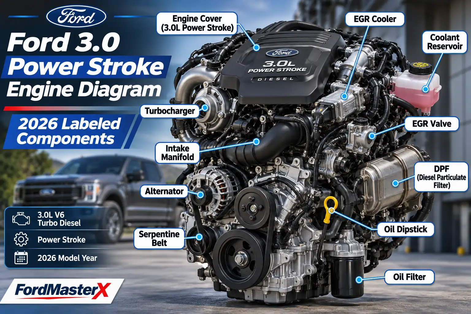
Ford 3.0 Power Stroke Engine Diagram: 2026 Labeled Components

The Ford 3.0 Power Stroke engine diagram helps you identify the major parts of the 2018–2021 F-150 diesel V6, from the turbocharger and fuel-injection system to the EGR cooler and exhaust aftertreatment.
The key is choosing the right diagram: an engine illustration identifies assemblies, an under-hood drawing identifies service points, and a system schematic shows how air, fuel, and exhaust move.


Ford published all three kinds of reference material. Use the component guide below to interpret them without confusing a functional flow chart with a physical parts-location drawing.
3.0L Power Stroke V6: How 4 Engine Systems Connect
2018–2021 F-150 diesel • Simplified functional flow, not an under-hood parts-location map
EGR is a controlled branch, not an extra stage after the tailpipe. Its exact takeoff and return locations require the factory routing illustration.
How to Read the Ford 3.0 Power Stroke Engine Diagram


Start with the diagram’s viewing angle. An illustration of a bare engine may show the accessory-drive end facing you. An under-hood drawing looks down into the F-150’s engine compartment. A system schematic rearranges parts to make their connections easier to follow, so the distances and positions on that page are not mounting locations.
Ford’s original 3.0L Power Stroke engine illustration and specifications identify the primary mechanical assemblies. Its labels include the turbocharger, secondary fuel filter, high-pressure injection system, EGR equipment, iron block, and structural oil pan.
| Reference Type | What It Identifies | Best Use |
|---|---|---|
| Engine illustration | Major parts on the engine assembly | Recognizing components and their general relationships |
| Under-hood overview | Fill points, reservoirs, battery, air filter, fuse box | Routine inspection and maintenance |
| Engine-system schematic | Airflow, fuel supply, EGR, emissions equipment, sensors | Understanding operation and diagnostic circuits |
A diagram may omit engine covers, brackets, and hoses for clarity. Match the engine family and model year before transferring any label to your truck. With the diagram type established, the first components to recognize are the engine’s core assemblies.


What Are the Key 3.0L Power Stroke Engine Components


The F-150’s 3.0L Power Stroke is a 60-degree, dual-overhead-cam turbo-diesel V6. Ford used a compacted graphite iron cylinder block, aluminum-alloy heads, a forged-steel crankshaft, and aluminum-alloy pistons. It is not the gasoline 3.0L V6 found in older Ford vehicles.
| Engine Detail | Ford 3.0L Power Stroke Reference |
|---|---|
| F-150 model years | 2018–2021 |
| Configuration | 60-degree V6, DOHC, turbocharged diesel |
| Displacement | 3.0 liters |
| Rated output | 250 hp at 3,250 rpm |
| Rated torque | 440 lb-ft at 1,750 rpm |
| Fuel injection | High-pressure common-rail direct injection |
| Advertised injection pressure | Up to 29,000 psi |
| Block and heads | Compacted graphite iron block; aluminum-alloy heads |
Turbocharger and Intake Hardware


The variable-geometry turbocharger uses exhaust energy to pressurize incoming air. Its adjustable turbine geometry helps the engine respond across a broad range of operating speeds. The charge-air plumbing and intercooler belong to this same airflow system, although not every piece is visible in a bare-engine illustration.
Block and Rotating Assembly


The block encloses the six cylinders. The crankshaft converts piston movement into rotation, while the structural oil pan supports the lower engine assembly. Ford also identifies a tuned elastomeric damper intended to reduce engine vibration.


Fuel and EGR Assemblies


The secondary fuel filter protects the downstream injection equipment. The high-pressure system feeds the fuel rails and injectors. The cooled exhaust gas recirculation system, or EGR, routes a controlled amount of exhaust back toward the intake to help manage emissions.
These assemblies explain the engine’s construction. Everyday maintenance starts with the service points you can identify under the hood.
Where Are the 8 F-150 Diesel Service Points


The 2018 Ford F-150 owner’s manual provides an under-hood overview specifically for the 3.0L V6 diesel. It uses eight lettered callouts. The labels below correspond to that Ford illustration, not to a generic F-150 gasoline engine photograph.


| Label | Ford Component | What to Look For |
|---|---|---|
| A | Power distribution box | Covered fuse and electrical distribution enclosure |
| B | Engine oil filler cap | Cap used for adding engine oil |
| C | Engine oil dipstick | Handle used to check engine oil level |
| D | Brake fluid reservoir | Brake-fluid container near the master-cylinder area |
| E | Air filter assembly | Air-cleaner housing feeding the intake system |
| F | Engine coolant reservoir | Coolant expansion and level-check container |
| G | Battery | Vehicle’s 12-volt battery |
| H | Windshield washer fluid reservoir | Washer-fluid fill point |
You can check the placement against Ford’s 2018 F-150 owner’s manual, under Under Hood Overview – 3.0L V6, Diesel, printed page 347.
The letters indicate service-point locations in that particular manual illustration. They do not identify the turbocharger, fuel pump, or EGR cooler. For a 2019, 2020, or 2021 truck, confirm the illustration against the manual for that model year before following a maintenance procedure.
If you are identifying the oil filler or dipstick before servicing the engine, the site’s Ford engine oil recommendation chart explains how Ford specification codes are organized. Use your exact model-year owner’s manual to confirm the correct diesel oil specification and quantity rather than substituting a gasoline-engine figure.
The air-filter housing is also the starting point for understanding how the turbocharged intake system works.
How Does the 3.0 Power Stroke Airflow System Work
The engine’s fresh-air path begins at the air filter. Filtered air passes through intake sensing, enters the turbocharger compressor, moves through the charge-air cooler, and reaches the intake manifold before entering the cylinders.
Fresh-air route: Air filter → intake sensing → turbocharger compressor → air-to-air intercooler → intake manifold → cylinders.
Air Filter and Intake Sensors



The air filter removes particles before air enters the induction system. Ford’s system schematic identifies a mass airflow sensor and intake-air temperature measurements. Those inputs help the engine control module estimate incoming air conditions.
Variable-Geometry Turbocharger
The turbine is driven by exhaust gas, while the compressor pressurizes fresh air. These are separate gas paths connected mechanically within the turbocharger. Do not assume that the turbo’s position on a schematic is its exact location behind the engine cover.
Intercooler and Intake Manifold
Compressed air passes through an air-to-air intercooler to reduce its temperature before it enters the engine. The intake manifold distributes that air to the two cylinder banks. Ford’s system schematic also shows EGR mixing and intake-control hardware associated with this path.
Understanding the air circuit makes the next diagram easier to read: the diesel fuel circuit supplies the injection event that takes place inside each cylinder.
How Does the 3.0 Power Stroke Fuel System Work
The 3.0L Power Stroke uses a low-pressure fuel-supply stage and a separate high-pressure common-rail injection stage. The low-pressure side delivers filtered diesel fuel; the high-pressure pump and rails supply the injectors.
Fuel-supply route: Fuel tank → lift and filtration equipment → engine-mounted secondary filter → high-pressure pump → fuel rails → injectors.
Low-Pressure Supply and Filters
Ford’s diesel fuel-system monitoring material shows a chassis-mounted diesel fuel conditioning module with lift-pump and primary-filter functions, followed by an engine-mounted secondary fuel filter. It also depicts water-management and fuel-return components. A system diagram explains this sequence but does not replace the F-150’s physical fuel-filter location instructions.
High-Pressure Pump and Fuel Rails
The injection pump raises fuel pressure for the common-rail system. The rails distribute pressurized diesel to the injectors, while rail-pressure sensing provides feedback to engine management. Ford advertised injection pressure up to 29,000 psi for the 3.0L engine.
Injectors and Fuel Return
Each cylinder has a diesel injector. The system also needs a return or leak-off route for fuel that is not injected, and the schematic identifies a fuel cooler in that circuit. The return path must not be mistaken for a second high-pressure feed line.
Safety: Never loosen a common-rail pipe or injector fitting to check for fuel while the engine is running. High-pressure diesel can penetrate skin. Fuel-system repairs require the correct model-specific pressure-release and cleanliness procedures, not just a component drawing.
After combustion, the exhaust stream powers the turbine and passes through emissions-control equipment.
How the 3.0 Diesel EGR and Exhaust Systems Connect
The 3.0L diesel has two related but distinct exhaust paths. One recirculates a controlled portion of exhaust through the EGR system. The other carries exhaust through the turbocharger and downstream aftertreatment before it exits the truck.
Cooled Exhaust Gas Recirculation
The EGR system directs a measured portion of exhaust back toward the intake. Its cooler reduces the temperature of that recirculated gas. The schematic also shows control valves, sensors, and associated intake hardware, but their symbols should not be used as a physical bolt-location map.
Oxidation Catalyst and Particulate Filter
In the downstream exhaust path, the diesel oxidation catalyst, or DOC, helps oxidize certain exhaust pollutants. The coated diesel particulate filter, labeled CDPF in Ford’s schematic, captures soot and is periodically regenerated under controlled operating conditions.
DEF Dosing and SCR Catalyst
The selective catalytic reduction system, or SCR, uses diesel exhaust fluid, also called DEF or urea solution, in the exhaust stream to reduce nitrogen oxides. Ford’s schematic places the urea-dosing equipment upstream of the SCR catalyst and includes exhaust-temperature, NOx, and particulate monitoring components.
Aftertreatment route: Turbocharger exhaust outlet → DOC → coated DPF → DEF dosing → SCR catalyst → downstream exhaust.
The exact hardware arrangement is best understood from the System Schematic 3.0L Chassis Certified, printed page 15 of Ford’s 2019 diesel OBD system-operation summary. It is a functional system map, not a photograph of the parts underneath the F-150.
The schematic also contains the cylinder-numbering reference needed to interpret misfire and engine-bank terminology.
Which Cylinders Fire First in the 3.0 Power Stroke
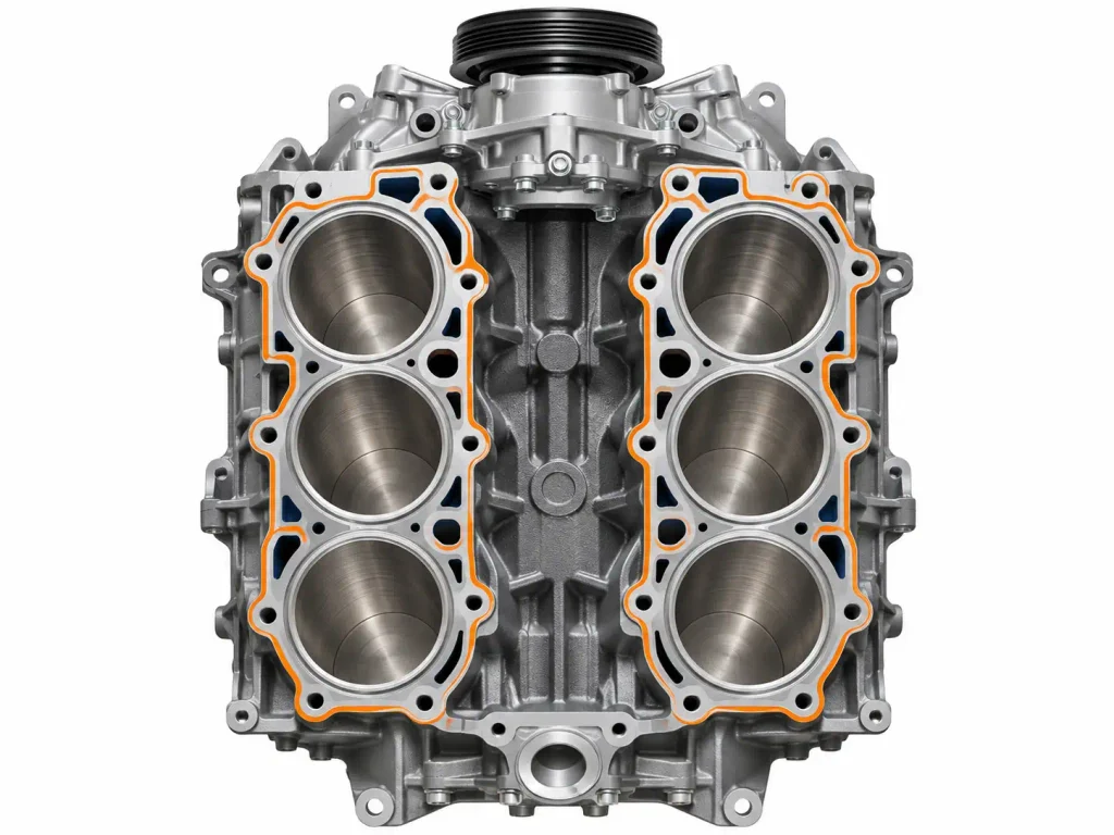
The verified 3.0L Power Stroke firing order is 1-4-2-5-3-6. That sequence describes when the six cylinders produce their combustion events, not how their physical positions are numbered.
Ford’s 3.0L engine schematic shows cylinders 1, 2, and 3 on one bank and 4, 5, and 6 on the other. In the F-150 installation, the passenger-side bank contains cylinders 1–3 and the driver-side bank contains cylinders 4–6. The cylinder nearest the front of the engine is number 1 on the passenger side and number 4 on the driver side.
| Position From Engine Front | Passenger Side, Bank 1 | Driver Side, Bank 2 |
|---|---|---|
| Front | Cylinder 1 | Cylinder 4 |
| Middle | Cylinder 2 | Cylinder 5 |
| Rear | Cylinder 3 | Cylinder 6 |
Firing sequence: 1 → 4 → 2 → 5 → 3 → 6.
Because this is a compression-ignition diesel, it uses injectors and glow-plug equipment rather than gasoline-engine spark plugs. When identifying a specific injector, glow plug, or cylinder-related fault, use the bank and cylinder numbers rather than a mirrored internet illustration.
That distinction helps prevent three common engine-diagram mistakes.
What 3 Diagram Identification Mistakes Should You Avoid
Confusing Diesel and Gasoline V6 Engines
A Ford 3.0L gasoline V6 diagram does not represent the F-150 3.0L Power Stroke. The diesel uses high-pressure common-rail injection, glow-plug equipment, a turbocharger, and diesel aftertreatment. Confirm the engine name, not just the displacement.
Substituting a 6.7L Power Stroke Diagram
The 6.7L Power Stroke is a V8 with a different cylinder layout and component architecture. The site’s Ford 6.7 Powerstroke engine diagram guide is useful for identifying that larger diesel, but its labels must not be transferred to the 3.0L V6.
Treating a Flow Schematic as a Parts Map
Ford’s emissions and fuel schematics organize components by their connections. A filter or sensor drawn beside the cylinders may actually be elsewhere in the truck. Use an under-hood diagram or model-specific repair illustration when you need an exact mounting location.
These checks establish which reference is appropriate before you inspect or service the engine.
What to Check Before Using an Engine Diagram
A Ford 3.0 Power Stroke engine diagram is useful only when you know what kind of information it represents. Ford’s component illustration identifies the major engine hardware. The owner’s manual provides practical under-hood service locations. The technical system schematic explains air, fuel, EGR, and exhaust connections.
Start by confirming that your truck has the 2018–2021 F-150 3.0L diesel V6. Next, orient the diagram from the front of the engine and identify the correct cylinder bank or system path. If you need to remove a part, use the model-year and VIN-specific service procedure to confirm mounting points, pressure-release instructions, and fastener specifications.
That approach turns a useful diagram into an accurate identification tool without confusing the 3.0L diesel with another Ford engine.
5 Common Questions About 3.0 Power Stroke Diagrams
Where Can I Find an Official Ford 3.0 Power Stroke Engine Diagram
Ford published a labeled 3.0L engine illustration in its 2018 engine fact sheet, an under-hood drawing in the F-150 owner’s manual, and a 3.0L system schematic in its 2019 diesel OBD documentation. Choose the illustration that matches whether you need physical component identification, service points, or system operation.
What Is the Firing Order of the 3.0 Power Stroke V6
The firing order is 1-4-2-5-3-6. Cylinders 1–3 are on the passenger-side bank and 4–6 are on the driver-side bank in the F-150, so distinguish cylinder position from firing sequence when checking an injector-related or cylinder-specific fault.
Where Is the Turbocharger on the 3.0 Power Stroke
The turbocharger is attached to the engine’s exhaust and intake systems, but a simplified diagram is not a reliable guide to its precise access point. Use the model-specific repair illustration before removing covers, hoses, or shields to reach it.
Does the 3.0 Power Stroke Have DPF and DEF Systems
Yes. The F-150 3.0L Power Stroke uses a diesel particulate filter and a DEF-based SCR aftertreatment system. Ford’s system schematic also identifies the oxidation catalyst and related exhaust sensors; the complete hardware path extends beyond the engine itself.
Is the 3.0 Power Stroke Diagram the Same as the 6.7 Power Stroke
No. The 3.0L is a V6 used in the 2018–2021 F-150, while the 6.7L is a larger V8 with different components and service access. Always match the diagram to the engine displacement, model year, and engine family before using it for diagnostics or repair.