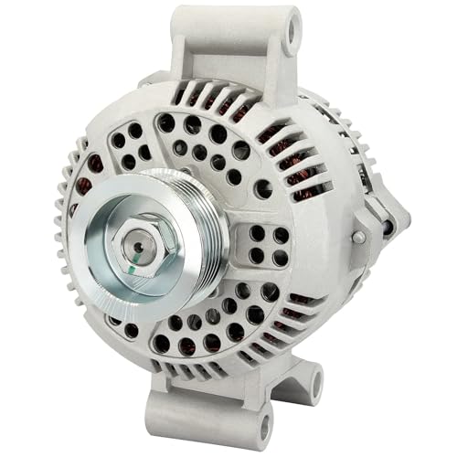
4 Wire Ford Alternator Wiring Diagram: Installation Setup 2026

The 4-wire Ford alternator connector typically utilizes an S (Sense) wire, an I (Ignition) wire, an A (Battery/Hot) wire, and an F (Field) wire. The S wire (usually yellow/white) senses battery voltage, the I wire (green/red) provides initial excitation, the A wire connects to the battery B+ post, and the F wire regulates field current.
📌 Key Takeaways
- Use 4-gauge or 6-gauge wire for the main B+ output to ensure current capacity.
- The ‘I’ terminal (Ignition) must receive 12V only when the key is in the ‘ON’ position.
- Verify 12.6V at the S-terminal with the engine off to ensure the voltage regulator is correctly sensing state-of-charge.
- A common failure point is the pin-to-terminal corrosion leading to high-resistance charging cycles.
- Seek professional auto-electric support if the dashboard ‘Battery’ light remains illuminated after verifying all four connections.
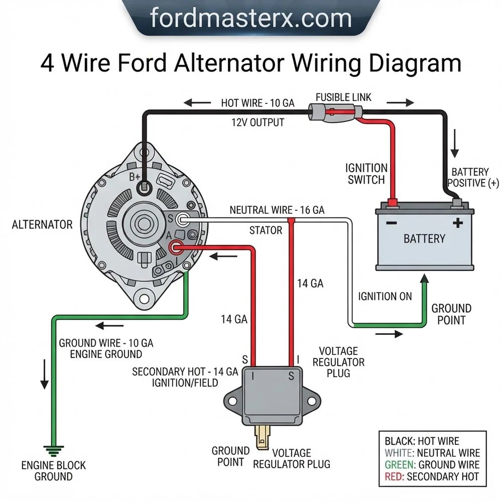
Proper management of a vehicle’s charging system relies entirely on understanding the specific pinout configuration of the alternator. For Ford vehicles equipped with 3G and 4G series charging systems, utilizing a 4 wire Ford alternator wiring diagram is essential for maintaining optimal battery health and preventing catastrophic electrical failures. These systems utilize sophisticated regulation involving a sensing circuit, ignition trigger, and high-amperage output to ensure the battery remains charged under varying load conditions. Incorrect pin assignment or inadequate wire gauge can lead to excessive heat, blown fusible links, or complete charging system failure. This guide provides the technical specifications required to interpret these circuits accurately, ensuring your equipment meets OEM charging performance standards.
Understanding the 4 Wire Ford Alternator Wiring Diagram Components
The 4 wire Ford alternator wiring diagram is centered around the external voltage regulation path. Unlike older, internally self-exciting units, the 3G and 4G alternators require specific inputs to function. The central B+ terminal serves as the primary output, which must be sized according to the alternator’s maximum amperage rating. Using an undersized cable here will cause significant voltage drop and may melt the insulation during sustained high-load operations.


The regulator plug typically contains three distinct signal pins. The S (Sense) wire is critical; it informs the voltage regulator of the actual system voltage at the battery side. It is designed to be a direct line back to the positive battery terminal or a power distribution block. If this wire is open or experiences high resistance, the regulator may overcharge the battery because it cannot accurately detect the voltage level at the distribution point.
The A (or sometimes I) terminal serves as the ignition trigger. This is the hot wire that signals the alternator to activate its field excitation sequence when the key is turned to the run position. Without a clean signal through this wire, the alternator will remain dormant. You should verify this circuit using a digital multimeter; it should show battery voltage only when the ignition switch is engaged.
Finally, the F (Field) wire or Stator terminal interacts with the internal field circuit to monitor duty cycle and rotor speed. In many 3G Ford configurations, the Stator terminal (often labeled STA) provides a feedback loop for the instrument cluster’s charge indicator light. Monitoring the voltage here is a key diagnostic step when troubleshooting a “no charge” condition. Ensure that all terminal connections are free of oxidation, as even minor resistance at the terminal block can lead to false readings for the regulator, resulting in erratic charging behavior. Always verify the gauge of the wire; for the B+ lead, 4 or 6 AWG is generally required for high-output models, while the signal wires can effectively utilize 16-18 AWG wiring.
Wire Color Reference Table for Ford 3G and 4G Alternators
The following table outlines the standard color coding often found in Ford OEM harnesses. Note that manufacturer variations may occur depending on the specific engine platform and model year. Always verify with a continuity test before finalizing connections.
| Terminal | Function | Typical Wire Color |
|---|---|---|
| B+ (Main Stud) | Battery Output (Hot) | Large Gauge Black/Orange |
| S (Sense) | System Voltage Monitor | Yellow/White |
| A/I (Ignition) | Excitation Signal | Green/Red |
| STA (Stator) | Field Monitor/Light | White/Black |
On some aftermarket wiring kits, colors may vary significantly. Always utilize a wiring diagram specific to your engine’s manufacturing year and verify function via the pin position rather than the wire insulation color alone.
How to Read the 4 Wire Ford Alternator Wiring Diagram Step by Step
1. Identify the B+ Stud: Locate the primary output stud on the back of the alternator. This is your hot wire connection. Ensure you use an appropriately sized terminal ring and torque the mounting nut to 10-12 Nm to ensure a low-resistance path.
2. Inspect the Fusible Link: The B+ circuit must contain a fusible link or high-amperage mega-fuse located between the alternator and the battery junction block. This protects the vehicle wiring in the event of an internal short. Never bypass this protection.
3. Wire the Sense Circuit: Connect the S terminal (Sense) to a consistent 12V power source. In optimal setups, this wire travels directly to the positive battery post or the main power distribution center. This wire should be a fused line to prevent electrical fires if the wire insulation is compromised.
4. Integrate the Ignition Trigger: Connect the A/I terminal to the switched ignition source. Verify that this wire carries battery voltage only when the key is in the “On” position. If this wire remains powered when the ignition is off, the alternator field will stay active, potentially draining the battery overnight.
5. Grounding Verification: While many modern alternators are case-grounded, verify the integrity of the engine block ground strap. A poor ground wire will cause the alternator to create a “dirty” electrical signal, which can interfere with engine management sensors and lead to fluctuating voltage readings.
6. Verify Output Voltage: Once all connections are made, start the engine. Use a multimeter at the battery posts to confirm a charging voltage between 13.8V and 14.5V. If the voltage remains below 12.6V, check the excitation signal on the A/I terminal again.
System operating voltage should be monitored at the battery. Anything under 13.5V at idle indicates a potential failure in the stator feedback loop or a degraded voltage regulator duty cycle.
Common 4 Wire Ford Alternator Wiring Diagram Problems and Fixes
Installation errors often stem from ignoring the specific voltage requirements of the regulator. Here are the common failure points encountered during maintenance:
Voltage Regulator Duty Cycle Issues: If the regulator detects fluctuating voltage on the Sense line, it may enter a loop of attempting to compensate, causing “flickering” lights. This is usually caused by a poor connection or corrosion at the terminal block. Ensure all connectors are cleaned with electrical contact cleaner and treated with dielectric grease.
Stator Feedback Failure: A failed stator connection will often trigger the dash warning light. Check the White/Black wire path for breaks or shorts to the engine block. If the alternator passes a load test but the light remains on, the failure is almost certainly in the wiring harness or the bulb circuit itself.
High Resistance in the B+ Path: Over time, the crimp connector on the main output wire can oxidize. This adds resistance, causing the wire to become hot to the touch. This resistance confuses the sense circuit, leading to an over-voltage condition. Always replace old or brittle terminals to maintain clean conductivity.
Neutral Wire/Ground Path Obstruction: While the alternator grounds through its housing, paint or rust on the mounting bracket can prevent a solid connection. Ensure all mounting surfaces are clean metal-to-metal contacts. In some heavy-duty industrial equipment, adding a dedicated grounding wire from the alternator case to the engine block is recommended to eliminate interference.
* Fusible Link Fatigue: If the alternator is producing voltage but the battery is not receiving it, the fusible link has likely opened. This is common when the alternator is upgraded to a higher amperage model without upgrading the charge cable and the associated protection device.
Disconnect the negative battery cable before performing any electrical work on the alternator. The B+ terminal is live at all times, and accidental contact with the chassis will cause a direct short, potentially damaging the engine harness or causing a battery explosion.
4 Wire Ford Alternator Wiring Diagram Questions Answered
Can I bypass the Sense wire if it is damaged?
You should never bypass the Sense wire. It is the primary feedback mechanism that allows the voltage regulator to compensate for voltage drop across the vehicle’s electrical load. Operating without a functional sense connection usually leads to inaccurate charging or a “low voltage” warning status.


What is the purpose of the neutral wire connection on some units?
In certain 4-wire configurations, the fourth wire acts as a neutral or stator monitor. It provides a frequency signal that informs the ECU or instrument cluster about the alternator’s rotational speed, which is critical for systems that manage idle speed control under high electrical load.
Why is my alternator outputting high voltage (16V+)?
An over-voltage condition is almost always a result of a sensing circuit failure. If the regulator does not receive a voltage signal via the S (Sense) wire, it defaults to maximum output in an attempt to maintain a charge, which will eventually boil the electrolyte in your battery and destroy sensitive electronics.
Should I use a larger wire gauge than OEM?
If you have upgraded your alternator to a higher amperage output than the factory unit, you must increase the gauge of the B+ wire. Moving from a stock 130A unit to a 200A unit typically requires jumping from a 6 AWG to a 2 or 4 AWG cable to prevent voltage drop and thermal degradation of the harness.


Does the ignition wire need a relay?
The A/I ignition wire typically draws very low current (less than 1 amp) to trigger the regulator’s internal field circuit. A relay is generally not required, but ensure the circuit is protected by a standard fuse to prevent a catastrophic wiring failure if the alternator’s internal excitation path shorts to the ground.
Step-by-Step Guide to Understanding the 4 Wire Ford Alternator Wiring Diagram
Identify – Verify the alternator part number and match it against the pinout configuration.
Locate – Position the connector so the locking tab is upward to correctly identify the S, I, A, and F pins.
Reference – Cross-reference your harness wire colors with the OEM wiring diagram to ensure hot wire and ground wire continuity.
Connect/Route – Route the harness away from the exhaust manifold using high-heat thermal sleeves to prevent wire melting.
Verify – Use a digital multimeter to confirm 12V at the hot wire and verify the ground wire has less than 0.1 ohms resistance.
Troubleshoot – Test the system output while idling; if voltage remains below 13.5V, re-check the ignition excitation wire signal.
4 Wire Ford Alternator Wiring Diagram: Frequently Asked Questions


What wire color is the sense wire on 4 wire ford alternator wiring diagram?
The sense wire (S-terminal) is typically yellow or yellow/white. It connects directly to the battery or the main power distribution block to monitor system voltage. A poor connection here prevents the regulator from adjusting the output correctly, often resulting in an under-charged battery or flickering lights under load.
What do the pin numbers mean on 4 wire ford alternator wiring diagram?
Pin numbers correspond to the regulator plug housing. Pin 1 is often the I (Ignition) circuit, Pin 2 is the S (Sense) circuit, Pin 3 is the A (Hot) circuit, and Pin 4 is the F (Field) circuit. Always reference the plastic connector’s molded numbers for precise orientation before crimping.
How many wires does 4 wire ford alternator wiring diagram have?
As the name implies, there are exactly four active control wires in the regulator harness. However, note that these function alongside the heavy-gauge B+ output stud and the alternator housing ground wire. Do not confuse the control harness with the high-amperage output cable, which must be rated for the alternator’s total output.
What are common wiring mistakes with 4 wire ford alternator wiring diagram?
The most frequent error is reversing the Ignition and Sense wires. This causes the alternator to fail to excite or continuously drain the battery when the vehicle is parked. Additionally, failing to secure a clean ground wire to the alternator casing often leads to erratic voltage output and regulator failure.
Do I need a brake controller for 4 wire ford alternator wiring diagram?
No, a brake controller is completely unrelated to the alternator’s electrical output. A brake controller manages trailer braking systems, while the 4-wire alternator harness exclusively manages the vehicle’s internal charging loop. Mixing these circuits would lead to severe electrical shorts and potential damage to the vehicle’s engine control module.
What gauge wire does 4 wire ford alternator wiring diagram require?
The control harness typically uses 16-18 gauge wire for signal stability. However, the main B+ output wire connected to the alternator stud must be at least 4 or 6-gauge copper depending on the alternator’s amperage rating. Using undersized wiring for the main output will lead to dangerous heat buildup and fire hazards.
{
“@context”: “https://schema.org”,
“@type”: “FAQPage”,
“mainEntity”: [
{
“@type”: “Question”,
“name”: “What wire color is the sense wire on 4 wire ford alternator wiring diagram?”,
“acceptedAnswer”: {
“@type”: “Answer”,
“text”: “The sense wire (S-terminal) is typically yellow or yellow/white. It connects directly to the battery or the main power distribution block to monitor system voltage. A poor connection here prevents the regulator from adjusting the output correctly, often resulting in an under-charged battery or flickering lights under load.”
}
},
{
“@type”: “Question”,
“name”: “What do the pin numbers mean on 4 wire ford alternator wiring diagram?”,
“acceptedAnswer”: {
“@type”: “Answer”,
“text”: “Pin numbers correspond to the regulator plug housing. Pin 1 is often the I (Ignition) circuit, Pin 2 is the S (Sense) circuit, Pin 3 is the A (Hot) circuit, and Pin 4 is the F (Field) circuit. Always reference the plastic connector’s molded numbers for precise orientation before crimping.”
}
},
{
“@type”: “Question”,
“name”: “How many wires does 4 wire ford alternator wiring diagram have?”,
“acceptedAnswer”: {
“@type”: “Answer”,
“text”: “As the name implies, there are exactly four active control wires in the regulator harness. However, note that these function alongside the heavy-gauge B+ output stud and the alternator housing ground wire. Do not confuse the control harness with the high-amperage output cable, which must be rated for the alternator’s total output.”
}
},
{
“@type”: “Question”,
“name”: “What are common wiring mistakes with 4 wire ford alternator wiring diagram?”,
“acceptedAnswer”: {
“@type”: “Answer”,
“text”: “The most frequent error is reversing the Ignition and Sense wires. This causes the alternator to fail to excite or continuously drain the battery when the vehicle is parked. Additionally, failing to secure a clean ground wire to the alternator casing often leads to erratic voltage output and regulator failure.”
}
},
{
“@type”: “Question”,
“name”: “Do I need a brake controller for 4 wire ford alternator wiring diagram?”,
“acceptedAnswer”: {
“@type”: “Answer”,
“text”: “No, a brake controller is completely unrelated to the alternator’s electrical output. A brake controller manages trailer braking systems, while the 4-wire alternator harness exclusively manages the vehicle’s internal charging loop. Mixing these circuits would lead to severe electrical shorts and potential damage to the vehicle’s engine control module.”
}
},
{
“@type”: “Question”,
“name”: “What gauge wire does 4 wire ford alternator wiring diagram require?”,
“acceptedAnswer”: {
“@type”: “Answer”,
“text”: “The control harness typically uses 16-18 gauge wire for signal stability. However, the main B+ output wire connected to the alternator stud must be at least 4 or 6-gauge copper depending on the alternator’s amperage rating. Using undersized wiring for the main output will lead to dangerous heat buildup and fire hazards.”
}
}
]
}