
2018 Ford Expedition Fuse Box Diagram: 2026 Troubleshooting Guide

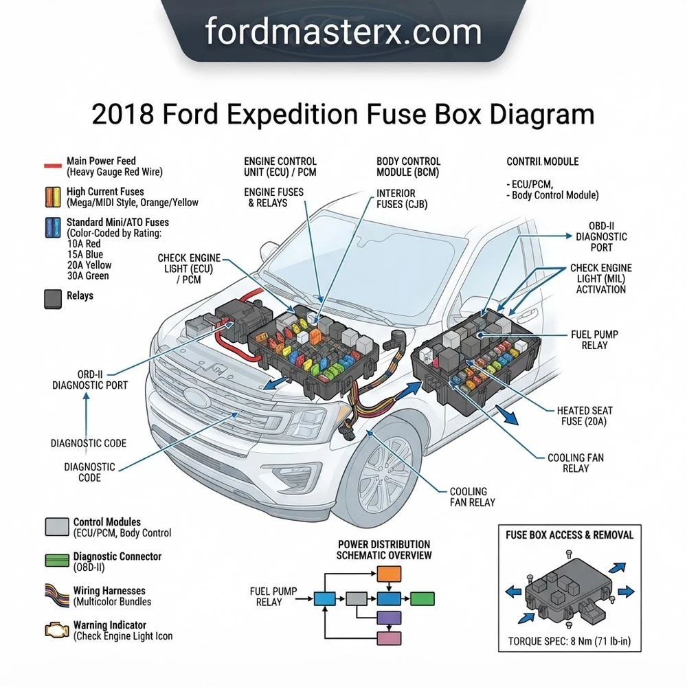
The 2018 Ford Expedition features two primary fuse panels: the Battery Junction Box (BJB) located under the hood and the Body Control Module (BCM) inside the passenger footwell. Refer to the diagram for specific 5A-60A fuse slot assignments to isolate electrical faults before running an OBD-II diagnostic code scan.
📌 Key Takeaways
- The BJB handles high-amperage circuits up to 60A for primary systems, while the interior BCM manages low-amperage cabin electronics.
- Always cross-reference the diagram with your vehicle’s specific trim level, as feature sets (e.g., heated seats) change slot configuration.
- Ensure all replacement fuses match the original amperage ratings exactly; never exceed torque specs for the 10mm ground cable connections during service.
- A common point of failure is moisture-induced corrosion on the BJB terminals, often mimicking a faulty ECU or failing alternator.
- If diagnostic code troubleshooting persists after a fuse swap, professional testing of the CAN-bus communication is required.
The 2018 Ford Expedition represents a sophisticated integration of high-voltage electronics and powertrain management, requiring precise knowledge of its electrical distribution network. For professional technicians and advanced DIYers, a deep understanding of the 2018 ford expedition fuse box diagram is essential for troubleshooting complex system failures. This vehicle utilizes a dual-power center architecture to manage everything from the ECU (Engine Control Unit) to climate control and advanced driver-assist systems. Misinterpreting these power distribution circuits can lead to transient electrical faults or irreversible damage to sensitive control modules. By analyzing the OEM-specified pinouts and circuit relay paths, you can efficiently isolate open circuits, shorts, or blown fuses that often manifest as phantom diagnostic codes.
Navigating the 2018 Ford Expedition Fuse Box Diagram Locations

The 2018 Ford Expedition utilizes two primary power distribution hubs. Locating these centers is the first step in any electrical diagnostic procedure. The Battery Junction Box (BJB), often referred to as the Power Distribution Box, is located in the engine compartment on the passenger side near the firewall. This unit handles high-amperage feeds directly from the battery and alternator, distributing power to the starter solenoid, cooling fans, and major powertrain control systems.


The secondary power center, known as the Body Control Module (BCM) or the Passenger Compartment Fuse Panel, is situated behind the passenger-side kick panel. Accessing this panel requires the removal of the trim cover to expose the fuse array responsible for cabin electronics, including the infotainment system, power seats, and interior lighting.
Understanding the Battery Junction Box (BJB) Layout

The BJB contains both mini-blade fuses and high-amperage cartridge fuses. When reviewing the 2018 ford expedition fuse box diagram for the BJB, pay close attention to the fuse rating colors and their specific circuit assignments. High-current circuits, such as the fuel pump relay or the cooling fan control module, are frequently protected by J-case cartridge fuses. If a customer reports a “no start” condition or signs of intermittent oil pressure drop alerts on the cluster, checking the main BJB ignition relay is the correct diagnostic starting point.
Accessing the Body Control Module (BCM) Panels


The interior panel contains the logic-level fuses for the cabin. It is critical to recognize that this module communicates directly with the ECU via the CAN-bus. If you are experiencing communication errors or a persistent check engine light that correlates with body-related diagnostic codes, ensure that the BCM has stable voltage input. Using the diagram to verify the integrity of the BCM power supply fuses can prevent unnecessary module replacement.
When testing the BCM, ensure your automotive multimeter is set to a high-impedance mode to prevent triggering a false diagnostic code within the sensitive CAN-bus network.
Common 2018 Ford Expedition Electrical Symptoms and Failures


Electrical anomalies in the 2018 Ford Expedition are rarely random; they are typically the result of thermal degradation at a contact point or a failed relay switch. By mapping these symptoms to specific circuit locations in the 2018 ford expedition fuse box diagram, you can accelerate your diagnostic workflow.
| Symptom | Primary Suspect | Diagnostic Focus |
|---|---|---|
| Engine Cranks but No Start | Fuel Pump Fuse (BJB) | Voltage at Pump Connector |
| Check Engine Light (P0685) | PCM Power Relay | Relay Contact Resistance |
| Coolant Fan Inoperative | Cooling Fan J-Case Fuse | Load Testing the Circuit |
| Interior Accessory Failure | BCM Circuit Breaker | Visual Fuse Continuity Test |
Relay and Fuse Integrity Protocols
Relays are electromechanical devices prone to pitting over time. If a relay clicks but the load does not activate, check for oxidation at the blade terminals. A voltage drop greater than 0.5V across the relay contacts indicates a failure that requires replacement. Do not attempt to bypass these relays with jumper wires, as this can trigger a protective state in the ECU or cause irreparable damage to the circuit board traces within the fuse panel.
Diagnostic Procedures for the 2018 Ford Expedition Fuse System
To accurately diagnose issues using the 2018 ford expedition fuse box diagram, you must approach the electrical system with a standardized testing methodology. Start by using an OBD-II diagnostic scanner to pull any pending or stored diagnostic code. Cross-reference these codes with the fuse box layout to see if multiple unrelated modules share a common power feed or ground point.
1. Scan for Trouble Codes: Utilize a professional-grade OBD-II scanner to identify modules that are not communicating. If an entire bank of electronics is offline, the issue likely resides at the main feed or a high-amperage fuse.
2. Visual Inspection: Pull suspect fuses using a proper fuse puller tool. Inspect for the characteristic “S” shaped burn mark on the metal element.
3. Voltage Drop Testing: With the circuit under load, measure the voltage drop across the fuse terminals. A reading of 0V is ideal; any significant voltage differential indicates high resistance.
4. ECU Communication Verification: If the ECU fails to communicate, check the PCM power relay and its associated fuse path. Verify the ground integrity at the chassis connection.
5. Sensor Correlation: If you are seeing sensor-related faults—such as oil pressure or coolant flow inconsistencies—ensure that the sensor’s dedicated power supply fuse is not providing intermittent voltage, which can cause erratic sensor signal interpretation.
Never replace a fuse with a higher amperage rating than specified. This overrides the vehicle’s inherent electrical safety design and poses a severe fire risk due to potential short circuits.
Advanced Tools for Circuit Isolation


When a fuse blows repeatedly, you have a short circuit. Avoid the “fuse-burning” method of troubleshooting. Instead, use a short finder tool or a multimeter set to resistance (Ohms) to locate the path to ground. Disconnect the load at the component end and monitor the circuit for continuity to the chassis. This methodology prevents the catastrophic failure of additional electrical components during the diagnostic process.


Critical Maintenance and Safety for 2018 Expedition Power Systems


Maintaining the electrical integrity of the 2018 Ford Expedition requires attention to environmental factors. Electrical systems are subject to corrosion, particularly in climates where road salt or humidity is prevalent. Ensure that the fuse box covers are sealed tightly to prevent moisture intrusion, which can lead to electrolytic corrosion of the copper contacts.
Periodic Inspection: Inspect the BJB for signs of white or green crusting on the fuse blades, which indicates moisture-induced oxidation.
Proper Cleaning: If corrosion is found, use an electronic contact cleaner and a soft-bristle brush. Do not use abrasive tools that could remove the anti-corrosive plating from the fuse terminals.
Battery Health: Ensure the battery terminal torque spec is maintained to avoid voltage fluctuations that can induce false diagnostic code triggers across the CAN network.
Component Servicing: If you are performing major engine work, such as a timing chain replacement, ensure the engine harness grounds are disconnected and re-torqued to OEM specifications. Improper grounding is a primary cause of mysterious electrical system malfunctions.
Refer to the Ford service manual for the exact torque spec on engine block ground straps, typically 12-15 Nm, to ensure solid electrical continuity for the ECU and powertrain sensors.
2018 Ford Expedition Fuse Box Diagram Questions Answered
Can a blown fuse cause a check engine light to stay on?
Yes, a blown fuse supplying power to the ECU or a critical sensor will trigger a diagnostic code. If the sensor power circuit is open, the ECU will register the loss of signal as a failure, illuminating the check engine light. Always check the 2018 ford expedition fuse box diagram for the relevant powertrain control module fuses before replacing expensive sensors.


Why does my fuse blow immediately after replacement?
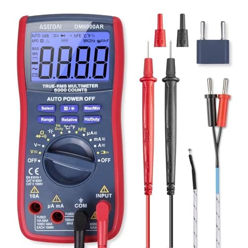


An immediate failure upon installation indicates a dead short circuit to ground. The current flow exceeds the fuse rating instantly. You must use a multimeter to isolate the wiring harness segment or the component that has shorted out before installing a new fuse.
What is the difference between blade and cartridge fuses in this model?
Blade fuses are used for low-amperage control circuits (5A to 30A), while cartridge fuses are designed for high-current applications (40A and above), such as cooling fans or the starter motor relay. They are physically designed to dissipate more heat under load.
How do I know if a relay is faulty?
A faulty relay will often cause the device it controls to either stay on constantly or not function at all. You can use an automotive multimeter to test the resistance across the relay coil terminals. If the coil is open or shorted, the relay must be replaced. Refer to the layout in your diagram for specific relay part numbers.
Step-by-Step Guide to Understanding the 2018 Ford Expedition Fuse Box Diagram
Identify – Verify your specific model trim to ensure the correct fuse diagram version.
Locate – Open the engine bay BJB cover or the interior BCM panel in the passenger footwell.
Reference – Match the specific component fault with the fuse number on the diagram grid.
Connect/Route – Use a multimeter to check for voltage across the suspected fuse terminals.
Verify – Perform an OBD-II diagnostic scan to confirm the fault code clears after the repair.
Troubleshoot – Inspect wiring looms for chafing if the fuse continues to blow immediately upon replacement.
{
“@context”: “https://schema.org”,
“@type”: “FAQPage”,
“mainEntity”: [
{
“@type”: “Question”,
“name”: “What does the 2018 ford expedition fuse box diagram show?”,
“acceptedAnswer”: {
“@type”: “Answer”,
“text”: “The diagram maps the physical layout of the Battery Junction Box and interior fuse panel. It identifies specific fuse amperage ratings, relay functions for lighting, fuel systems, and ignition, and provides the visual reference needed to trace power supply paths for sensitive electronics like the ECU.”
}
},
{
“@type”: “Question”,
“name”: “How do I read the 2018 ford expedition fuse box diagram?”,
“acceptedAnswer”: {
“@type”: “Answer”,
“text”: “Locate the diagram inside your owner’s manual or on the underside of the fuse box cover. Match the numerical slot ID from the cover to the printed chart. Use a multimeter set to continuity mode to verify if a fuse is blown, rather than relying solely on visual inspection.”
}
},
{
“@type”: “Question”,
“name”: “What are the main components in 2018 ford expedition fuse box diagram?”,
“acceptedAnswer”: {
“@type”: “Answer”,
“text”: “The system includes the Power Distribution Box (engine bay) containing high-current fuses and relays, and the Smart Junction Box (interior). Key components mapped include fuel pump relays, ignition coils, ABS module circuits, and the diagnostic link connector interface for OBD-II hardware.”
}
},
{
“@type”: “Question”,
“name”: “What are common problems with 2018 ford expedition fuse box diagram?”,
“acceptedAnswer”: {
“@type”: “Answer”,
“text”: “Common issues include intermittent power to infotainment, lighting, or engine management systems. Often, a ‘check engine light’ is triggered by a blown PCM-related fuse. Corrosion in the engine bay box is frequent; if cleaning terminals doesn’t resolve the fault, suspect a relay failure or wiring break.”
}
},
{
“@type”: “Question”,
“name”: “Can I use 2018 ford expedition fuse box diagram for DIY repair?”,
“acceptedAnswer”: {
“@type”: “Answer”,
“text”: “Yes, it is the primary resource for troubleshooting electrical dead-zones. However, avoid probing terminals with thick metal objects to prevent pin damage. For advanced repairs involving the ECU or internal bus systems, ensure you have a proper torque spec guide for any mounting bolts removed during service.”
}
},
{
“@type”: “Question”,
“name”: “What tools do I need for 2018 ford expedition fuse box diagram?”,
“acceptedAnswer”: {
“@type”: “Answer”,
“text”: “You will need a plastic fuse puller (non-conductive), a digital multimeter for voltage and resistance testing, and a quality OBD-II scanner. A set of terminal cleaners is also useful if you identify corrosion as the primary cause of a recurring diagnostic code.”
}
}
]
}