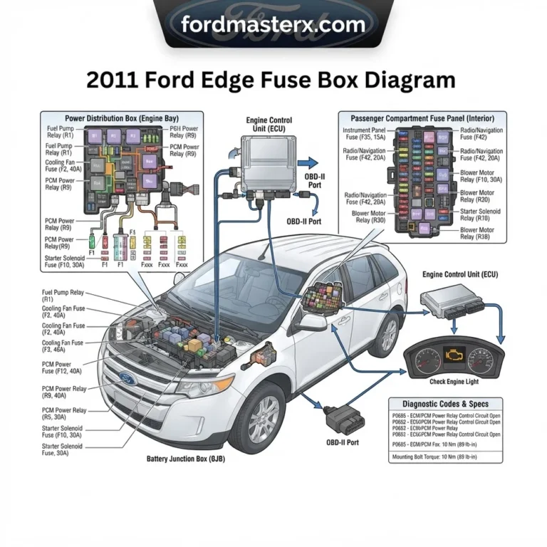
2017 Ford Edge Fuse Box Diagram: 2026 Troubleshooting Guide

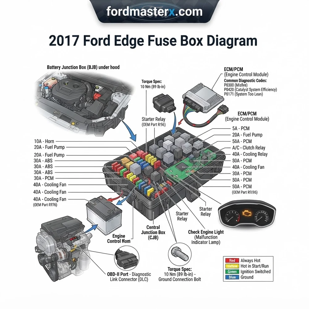
The 2017 Ford Edge utilizes two primary power distribution centers: the Battery Junction Box located in the engine compartment and the Body Control Module (BCM) in the passenger footwell. Refer to the internal cover legend for specific mini and J-case fuse locations corresponding to the ECU and fuel pump circuits.
📌 Key Takeaways
- The BCM handles interior accessories, while the Battery Junction Box manages high-amperage components like the starter and cooling fan.
- Always match amperage ratings exactly; replacing a 10A fuse with a 20A can lead to permanent harness damage.
- When performing electrical repairs, ensure terminal connections are tightened to manufacturer torque specs to prevent voltage drops.
- The most common failure point is moisture intrusion causing corrosion at the BCM connector pins.
- If the check engine light persists after a fuse replacement, utilize an OBD-II scanner to clear the diagnostic code before further testing.
Maintaining the electrical integrity of a 2017 Ford Edge requires a precise understanding of the Power Distribution Box and the Body Control Module. When components such as the ECU fail to communicate, or the check engine light illuminates due to an intermittent diagnostic code, the primary point of failure is often found within the fuse layout. This guide serves as a comprehensive reference for mapping the electrical architecture of your vehicle. By utilizing the 2017 Ford Edge fuse box diagram correctly, technicians can isolate faulty circuits, verify ground integrity, and prevent costly damage to sensitive control modules, ensuring the vehicle remains within OEM operational parameters.
Locating the 2017 Ford Edge Fuse Box Diagram Points
Recommended Best Deal Products


The 2017 Ford Edge utilizes a dual-location electrical architecture. Identifying these physical zones is the first step in effective troubleshooting. The primary Power Distribution Box is located in the engine compartment on the driver’s side, positioned near the cowl. To access it, you must release the two retaining clips and lift the cover vertically to prevent bending the connector pins. This box handles high-amperage feeds for the powertrain and cooling systems, including the ECU and fuel pump modules.
The second electrical center is the Body Control Module (BCM), situated behind the glove box assembly in the passenger footwell. This unit manages the comfort, lighting, and convenience features. Accessing the BCM often requires removing the lower trim panel and unhooking the glove box damper, which can be sensitive to aggressive handling. When investigating issues like erratic oil pressure sensor readings or timing chain actuator failures, ensure you are testing the correct module, as the interdependency between the BCM and the ECU is significant.
Technicians must utilize a plastic fuse puller tool to avoid damaging the delicate plastic housings of the micro-fuses. Metal pliers can cause short circuits or introduce microscopic fractures in the fuse element, leading to later failures. Always verify the current state of the terminal before extraction. If you are tracking a diagnostic code related to coolant flow or engine temperature, check for localized corrosion in the relay sockets of the engine bay fuse box. Using a multimeter at these specific junction points will help you distinguish between a blown component and a deeper wiring harness fault, saving significant shop time during complex repairs.
Always disconnect the negative battery terminal before performing invasive electrical work on the BCM to avoid accidental deployment of SRS components or triggering a false diagnostic code.
Understanding 2017 Ford Edge Fuse Box Diagram Symbols

Interpreting the 2017 Ford Edge fuse box diagram requires familiarity with standard automotive electrical symbology. The diagram relies on alphanumeric indices that correspond to the physical fuse slots. Each slot is designated by a specific amperage rating, indicated by both a numerical label and a color-coded body, as defined by the SAE J1284 standard. Deviating from these manufacturer-specified values can lead to severe thermal damage to the wire harness or, in extreme cases, electrical fires.
| Symbol/Index | Component Type | Typical Function |
|---|---|---|
| F1-F20 | Micro/Mini Blade Fuse | Low-current sensors, interior lights |
| R1-R15 | ISO Micro Relay | Cooling fan, fuel pump, ignition |
| D1-D5 | Protection Diode | Reverse polarity protection |
| J1-J10 | J-Case High-Amp | Main power supply to ECU/BCM |
When you consult the owner’s manual to translate the diagram, focus on the specific relay pins. Relays are essentially remote switches controlled by the ECU. If a relay clicks but the circuit remains open, the issue likely resides in the load side of the circuit, not the trigger side. For complex diagnostics involving the timing chain sensors or oil pressure switches, verifying that the relay is sending power to the component is a mandatory step before proceeding to mechanical tear-downs.
Common 2017 Ford Edge Fuse Box Diagram Issues and Symptoms
Recommended Best Deal Products


Failure to recognize when an electrical issue is fuse-related vs. mechanical can lead to unnecessary component replacement. If your vehicle exhibits a check engine light accompanied by a “No Communication” diagnostic code, do not immediately replace the ECU. Start by examining the relevant fuses in the engine compartment diagram. A failure in the main power distribution circuit often manifests as a total system shutdown or non-start condition, while localized issues like a malfunctioning infotainment screen usually trace back to the BCM.
- No Start/No Crank: Frequently caused by a blown main fuse in the Power Distribution Box, indicating a short in the starter circuit or ignition relay.
- Persistent Check Engine Light: If a specific sensor circuit (e.g., O2 sensor or timing chain solenoid) has no power, the fuse may have opened due to a pinched wire in the harness.
- Communication Errors: Intermittent OBD-II scan tool connectivity issues often arise from oxidized pins at the fuse box junction or a damaged BCM ground.
- Cooling System Inefficiency: An inoperative cooling fan is often traced back to a failed high-amp relay rather than the motor itself. Always verify the relay voltage drop before assuming motor failure.
- Erratic Gauges: Fluctuating oil pressure or temperature readings are often symptoms of a loose connection at the fuse block header, rather than a failure of the sensor units.
Never bridge a blown fuse with wire or conductive metal. This removes the only line of defense between your electrical system and a potential vehicle fire.
Diagnosis Steps for 2017 Ford Edge Fuse Box Diagram Circuits
Systematic diagnosis is required when dealing with complex Ford electrical systems. Begin by verifying the battery state of charge; a low-voltage condition (under 12.4V) can cause logic errors in the ECU, leading to phantom diagnostic codes. Once you have cleared the system with an OBD-II scanner, monitor the live data stream while wiggling the harness near the fuse box to see if the signal drops, which indicates a loose terminal.
- Visual Inspection: Remove the suspect fuse using a non-conductive fuse puller tool. Inspect the wire element inside the plastic housing. An open wire indicates a circuit overload or a direct short to ground.
- Multimeter Voltage Check: Set your multimeter to DC Volts. Probe the two test points on the top of the fuse while it is installed. If you see battery voltage on one side but 0V on the other, the fuse is blown. If you see 0V on both, check for a failed relay or an open upstream switch.
- Continuity Testing: With the battery disconnected, set the multimeter to the Ohms/Continuity setting. Test from the load side of the fuse socket to the component connector. A reading exceeding 0.5 ohms suggests excessive resistance or corrosion in the wiring harness.
- Ground Verification: Inspect the chassis ground points near the fuse box. A poor ground is a frequent cause of “ghost” codes that involve multiple systems simultaneously. Ensure the torque spec for the ground bolt is within OEM limits—typically 12-15 Nm for these chassis studs.
- Component Verification: If the circuit tests healthy up to the component, perform a back-probe test at the sensor itself to ensure power is reaching the actuator or monitoring device.
When replacing a blown fuse, always use the exact amperage rating specified in the owner’s manual. A higher amperage fuse can allow the circuit to overheat, melting the insulation and causing permanent harness failure.
2017 Ford Edge Fuse Box Diagram Questions Answered
Recommended Best Deal Products


Can a blown fuse cause a permanent diagnostic code to trigger?
Yes. If a sensor circuit—such as those monitoring timing chain position or oil pressure—loses power, the ECU will register an immediate open-circuit diagnostic code. Replacing the fuse will usually clear the electrical fault, but the code may remain in the “stored” or “history” memory until it is cleared via an OBD-II scan tool.
What should I do if the fuse box shows signs of heat damage or melted plastic?
Heat damage at a fuse terminal indicates high resistance, usually caused by a loose connection or oxidation. In this scenario, simply replacing the fuse is insufficient. You must inspect the terminal for corrosion and potentially replace the fuse box connector or the entire distribution block to prevent a recurrent electrical fire hazard.
Is it necessary to reset the ECU after replacing a major system fuse?
Typically, no. The ECU is designed to resume normal operation once power is restored. However, if you have disconnected the battery to perform a deep repair, the idle re-learn process may be required. This involves allowing the engine to idle for several minutes to allow the ECU to stabilize the fuel-air mixture and coolant flow parameters.
Do the engine bay and passenger compartment fuses share grounds?
While the power sources are distinct, many secondary grounds are shared at common chassis points. If you are experiencing electrical issues in both boxes simultaneously, prioritize testing the main body-to-engine ground strap, as a failure here will impact both the BCM and the engine-side ECU circuitry.
By following these diagnostic procedures and respecting the electrical specs provided, you can resolve the majority of electrical faults found in the 2017 Ford Edge. Always refer to the most current service manual for specific wire color codes, as these can vary slightly based on the manufacturing date and the specific engine trim package installed in your vehicle.
Step-by-Step Guide to Understanding the 2017 Ford Edge Fuse Box Diagram
Identify – Locate the fuse box cover and verify the orientation against your specific 2017 trim level manual.
Locate – Access the BCM in the passenger footwell or the BJB under the hood, depending on the failed component.
Reference – Use the diagram to pinpoint the exact slot number and amperage rating for the circuit you are testing.
Connect – Use a multimeter or test light to verify power at the test points on top of the fuses without removing them.
Verify – Pull the suspect fuse and inspect the metal element; if broken, replace it with one of the identical amperage and color.
Troubleshoot – Clear any existing diagnostic code using an OBD-II scanner and test the system for consistent performance.