
2003 Ford Windstar Fuse Box Diagram: Repair 2026

The 2003 Ford Windstar features two primary fuse panels: the interior Junction Box located under the instrument panel on the driver’s side and the Power Distribution Box in the engine compartment. The diagram identifies specific relay positions for the ECU, fuel pump, and cooling fans, critical for clearing diagnostic codes.
📌 Key Takeaways
- The Power Distribution Box houses high-amperage fuses (up to 60A) protecting main circuits.
- Verify circuit continuity using a multimeter set to ohms to identify blown fuses.
- Always observe a 5-10 ft-lbs torque spec if removing ground straps near the fuse block.
- Corroded pins at the ECU interface are a frequent failure point misidentified as a blown fuse.
- Consult a professional if the OBD-II port lacks power, as this often indicates a PCM communication failure.
The 2003 Ford Windstar represents a complex era of electrical integration for Ford’s minivan platform. Maintaining this vehicle requires a precise understanding of the Power Distribution Box (PDB) and the Central Junction Box (CJB). Because these systems manage everything from the ECU logic to climate control modules, identifying the correct fuse or relay is critical when diagnosing persistent electrical gremlins. Whether you are chasing a ghost drain in the lighting circuit or resolving a failure in the powertrain control module’s power feed, having an accurate 2003 Ford Windstar fuse box diagram is the cornerstone of effective repair. Proper diagnostic procedures prevent damage to delicate solid-state components and ensure the integrity of the vehicle’s wiring harness.
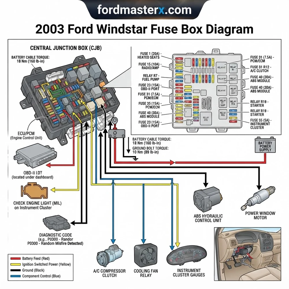
2003 Ford Windstar Fuse Box Diagram: Component Identification

The electrical architecture of the 2003 Windstar relies on two primary hubs. The Power Distribution Box (PDB), located in the engine compartment near the driver-side fender, houses high-amperage fuses and relays that manage primary power flow from the battery and alternator. The Central Junction Box (CJB), often referred to as the interior fuse panel, is located under the instrument panel on the driver side. It manages lower-amperage circuits for cabin accessories, instrument clusters, and secondary ECU sensor feeds.


When utilizing a 2003 Ford Windstar fuse box diagram, technicians must distinguish between these modules. High-amperage components—such as the fuel pump relay, ignition switch, and blower motor—are exclusively handled by the PDB. Conversely, the CJB manages auxiliary systems, such as the OBD-II diagnostic port power and interior lighting. Always cross-reference your specific vehicle build date, as late-2003 production models may feature minor revisions to relay configurations compared to early-year releases.
| Fuse/Relay | Location | Function/Circuit |
|---|---|---|
| Fuse 1 (30A) | PDB | Powertrain Control Module (PCM) Main Power |
| Relay 1 | PDB | Fuel Pump Control Logic |
| Fuse 12 (15A) | CJB | OBD-II Port / Diagnostic Data Link |
| Fuse 18 (20A) | CJB | Instrument Cluster/Transmission Control |
Never substitute a fuse with a higher amperage rating than specified on the diagram. Doing so creates an “open” protection scenario where the wire insulation can melt before the fuse blows, leading to catastrophic harness shorts or electrical fires.
Common 2003 Ford Windstar Fuse Box Diagram Issues and Symptoms


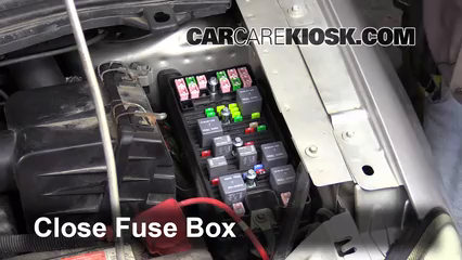
Electrical failure in the 2003 Windstar often stems from oxidation at the terminal connection points or moisture intrusion into the CJB. When the fuse box experiences thermal stress, the plastic housing may warp, causing poor contact for blade-style fuses. Understanding the relationship between these symptoms and the diagram is vital for accurate triage.
Intermittent ECU Power Loss: If the vehicle stalls unexpectedly or refuses to start, check the PCM power relay in the PDB. Often, corrosion on the relay pins mimics a failed sensor.
Non-Communicating OBD-II Port: If your scan tool fails to connect to the ECU, the diagnostic circuit is likely open. Inspect Fuse 12 in the CJB; this circuit is shared with the cigar lighter and is frequently overloaded by aftermarket chargers.
Blown Fuse Recurrence: A fuse that blows immediately upon replacement suggests a hard short-to-ground. Use the diagram to isolate the circuit branch and verify wire continuity using a multimeter.
Terminal Fretting: Over time, vibrations cause micro-arcing at the fuse terminals. If you notice discoloration or melting on the fuse blade, the entire contact block must be inspected for heat damage.
Before performing any electrical work, disconnect the negative battery terminal. The 2003 Windstar uses sensitive airbag and SRS components that can be triggered by sudden voltage spikes if the battery is connected during circuit testing.
Diagnostic Steps for 2003 Ford Windstar Electrical Failures


Troubleshooting the electrical system requires a logical approach, starting from the power source and moving toward the load. Do not rely on visual inspection alone, as modern fuses can fail internally without showing a broken element.
1. Isolation and Testing: Begin by using an automotive multimeter set to DC Voltage. Measure battery voltage at the B+ terminal of the PDB. It should read between 12.6V and 12.8V with the engine off.
2. Continuity Verification: To test a suspect circuit, remove the fuse and set your multimeter to the continuity (beep) setting. Place the probes on the fuse terminals. If the meter does not beep, the fuse has an open circuit.
3. Circuit Breaker Inspection: The Windstar utilizes integrated circuit breakers for power windows and seat adjustments. If these systems fail, feel the breaker for excessive heat. If it is hot to the touch, a short exists in the door harness or motor assembly.
4. Relay Logic Testing: To test a relay, apply 12V power to the coil pins (usually 85 and 86) and verify continuity between the switch pins (30 and 87). A “click” indicates the solenoid is actuating, but verify electrical flow with the multimeter to ensure the internal contacts are not pitted or carbon-fouled.
5. Harness Inspection: If the fuse is intact but the component remains inoperative, the issue is likely downstream. Trace the wiring harness color-coded in your service manual, looking for signs of chafing or heat-related insulation damage near engine-to-chassis grounding points.
6. Load Testing: For circuits managing high-draw components like cooling fans, perform a voltage drop test. A drop greater than 0.5V across the circuit indicates excessive resistance, often caused by corroded connections or an undersized repair wire.
Diagnostic port supply voltage: 12.0V – 14.5V. Terminal contact tension should be verified using a specialized terminal drag tool to ensure at least 2.0 lbs of insertion force for reliable sensor data transfer.
2003 Ford Windstar Maintenance and OBD-II Context
The 2003 Windstar relies on an interconnected system where fuse health directly impacts the ECU’s ability to manage engine parameters. A common diagnostic error involves chasing a “check engine light” for a sensor fault when the actual issue is a low-voltage supply to the PCM. When the ECU detects an erratic signal or an open circuit in a sensor line, it logs a Diagnostic Trouble Code (DTC).
If you see codes related to “Sensor Reference Voltage Low,” check the fuse panel diagram for the specific fuse powering the powertrain sensors. Often, this is a 10A or 15A circuit that also supplies the secondary fuel injectors or ignition coils. Maintaining stable voltage is essential for managing the timing chain and oil pressure monitoring systems, which rely on precise ECU inputs. If your vehicle exhibits high-rpm hesitation or poor fuel economy, verify that your electrical system is providing clean, stable power. Voltage spikes or dips can interfere with the OBD-II bus, causing “ghost” codes that point to failed components that are, in fact, perfectly functional. Before replacing expensive sensors or mechanical hardware, always verify that your electrical foundations—fuses, relays, and ground straps—are within manufacturer specs.


2003 Ford Windstar Fuse Box Diagram Questions Answered
Can I upgrade to a higher amperage fuse to prevent recurring blows?
No. You must never increase the fuse rating. The fuse is sized to protect the weakest link in the circuit, which is the wiring harness. Upgrading the fuse will lead to the wires melting and potentially catching fire before the fuse reaches its failure point.


Where is the OBD-II fuse located in the 2003 Windstar?


The OBD-II diagnostic port power is typically protected by the same fuse that handles the cigarette lighter or auxiliary power outlet in the Central Junction Box. Consult your specific diagram, but it is almost universally located in the interior cabin panel.
Why does my interior lighting flicker when I hit a bump?
This is a classic sign of a loose terminal connection or a failing relay in the CJB. Vibration causes a momentary disconnect in the circuit. Check the fuse box retention clips and ensure all relays are seated firmly in their sockets.
Does the 2003 Windstar have a main fusible link?


Yes, the PDB contains high-amperage fusible links or “maxi-fuses” that protect the entire electrical system from a direct alternator short. If your vehicle has total power loss, these are the first items to inspect.


How do I know if a relay is bad without a tester?
If you suspect a relay (e.g., fuel pump or A/C), you can often swap it with an identical relay from a non-critical system, such as the horn. If the horn stops working and the original problem disappears, you have confirmed the relay failure.
Step-by-Step Guide to Understanding the 2003 Ford Windstar Fuse Box Diagram
Identify – Consult the diagram to match the specific circuit suspected of failure.
Locate – Access the interior panel on the driver’s side or the under-hood Power Distribution Box.
Reference – Use the diagram’s legend to identify the corresponding fuse number and amperage rating.
Connect/Route – Test the fuse using a multimeter; if blown, replace only with the specified amperage.
Verify – Clear any existing diagnostic code using an OBD-II scanner and test the affected electrical system.
Troubleshoot – If the fuse blows repeatedly, inspect the wiring harness for shorts near the ECU or chassis ground.


