
2007 Ford Mustang Fuse Box Diagram: 2026 Troubleshooting Guide

The 2007 Ford Mustang features two primary fuse panels: the Smart Junction Box (SJB) located in the passenger-side kick panel and the Battery Junction Box (BJB) under the hood near the battery. Use these to diagnose power issues, monitor ECU voltage, or investigate a check engine light triggered by sensor failure.
📌 Key Takeaways
- The BJB houses high-amperage fuses ranging from 20A to 60A for main engine systems.
- Always verify the fuse puller tool is used to prevent terminal damage in the plastic housing.
- Ensure the battery is disconnected before servicing any fuse box modules to avoid short circuits.
- If replacing an ECU-related fuse, monitor for a diagnostic code to ensure the circuit stabilized.
- Seek professional diagnostic services if an electrical short leads to melted wiring or smoking.
The 2007 Ford Mustang, a cornerstone of the S197 platform, relies on a sophisticated electrical architecture to manage its powertrain, lighting, and convenience features. For technicians and advanced DIYers, mastering the 2007 Ford Mustang fuse box diagram is essential when troubleshooting intermittent electrical failures, non-responsive relays, or phantom power drains. Whether you are investigating an ECU communication error or diagnosing a persistent check engine light linked to a sensor circuit, the ability to pinpoint the exact fuse or relay location within the Battery Junction Box or the Smart Junction Box (SJB) is critical. This guide provides the technical reference data required to navigate these circuits efficiently and return the vehicle to factory operational specifications.
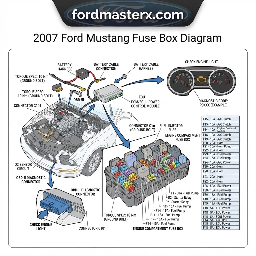
Navigating the 2007 Ford Mustang Fuse Box Diagram Layout

The electrical system of the 2007 Mustang is bifurcated into two primary distribution points. Understanding the physical geography of these modules is the first step in effective diagnostics. The Battery Junction Box (BJB) is located in the engine compartment, typically mounted on the passenger side near the firewall. This unit handles high-amperage feeds from the battery to major vehicle systems, including the starter motor, fuel pump, and main cooling fan relays. Accessing this panel requires careful manipulation of the plastic retaining clips; always inspect the seal to ensure moisture has not compromised the connections, which could lead to terminal corrosion and increased resistance.


Conversely, the Smart Junction Box (SJB) is situated in the passenger-side footwell, behind the kick panel. This module acts as the central gateway for body electronics, including the interior lighting, power windows, and communication with the ECU. When dealing with issues like a failed diagnostic code read or intermittent interior power, the SJB is the most common culprit. Because the SJB is sensitive to moisture ingress from cowl drain blockages, it is highly recommended to inspect this area for signs of oxidation whenever performing a routine electrical service.
Comparing BJB and SJB Circuit Roles

The BJB serves as the “power center” for high-load systems. If your vehicle exhibits issues with coolant flow due to a non-actuating fan, or if the oil pressure gauge remains flat due to a shorted sensor circuit, the BJB is your primary point of investigation. In contrast, the SJB manages lower amperage logic circuits. If the OBD-II port is not providing data, or if the check engine light is illuminated due to a loss of signal to the ECU, verify the SJB terminal integrity first. Always cross-reference your specific vehicle build date, as mid-year changes in the 2007 production cycle can occasionally lead to slight variations in relay assignments compared to the 2005 or 2006 models.
When testing circuits, use a high-impedance digital multimeter to prevent damage to the delicate solid-state components within the SJB. Standard test lights can inadvertently spike voltage and fry the internal logic gates.
2007 Ford Mustang Fuse Box Diagram: Component Identification


The following table details the primary high-current and logic-level circuits found within the 2007 Mustang distribution panels. These values are based on OEM electrical manuals and must be strictly adhered to during component replacement. Using an incorrect amperage fuse can lead to catastrophic harness damage or failure of the associated module.
| Circuit Function | Amperage | Box Location |
|---|---|---|
| PCM / ECU Power | 20A | BJB |
| Fuel Pump Module | 20A | BJB |
| OBD-II Data Link | 15A | SJB |
| Cooling Fan High Speed | 50A | BJB |
| Ignition Coil / Timing Circuit | 15A | BJB |
The S197 platform utilizes standard MINI and J-Case blade fuses. When replacing these, ensure the metal terminal is seated firmly; a loose fit can create an arc, leading to localized heating and potential melting of the fuse block plastic. If you discover a fuse that keeps blowing repeatedly, do not simply increase the fuse amperage. This indicates a dead short in the circuit path, often found in wire chafing near the timing chain cover or transmission housing.
Common 2007 Ford Mustang Fuse Box Diagram Issues and Symptoms
Electrical instability in the 2007 Mustang often presents with a specific set of diagnostic patterns. Recognizing these symptoms allows the technician to bypass time-consuming testing and focus directly on the faulty circuit path. The most frequent issues stem from excessive moisture in the passenger footwell or oxidation of the high-current terminals in the engine bay.
- No-Start Condition: If the starter relay is clicking but the engine fails to turn over, verify the BJB high-current fuse for the starter solenoid. If the ECU is not receiving power, check the PCM power relay located in the BJB.
- Erratic Engine Performance: If the vehicle experiences hesitation or stalls, verify the ignition coil circuit. A failing timing chain component may sometimes be misdiagnosed as an ignition issue, so confirm sensor signal integrity before tearing down the front end.
- OBD-II Communication Failure: A failure to connect a diagnostic tool often points to a blown fuse in the SJB that shares a circuit with the cigarette lighter or power point.
- Coolant Overheating: If the cooling fan fails to engage, test the fan relay circuit in the BJB. Verify that the coolant flow is not restricted before blaming the electrical system.
- Oil Pressure Warning: Persistent low-pressure light illumination, despite healthy physical oil pressure, may indicate a failed sensor ground path through the SJB interface.
Never replace a blown fuse with a higher amperage rating or a bypass wire. This bypasses the vehicle’s primary safety mechanism, creating a significant risk of vehicle fire and damage to the PCM/ECU.
Diagnosis Steps for 2007 Ford Mustang Electrical Circuits


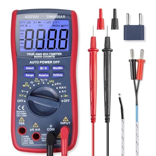
A methodical approach is required to diagnose complex electrical failures in the 2007 Mustang. Follow this systematic workflow to ensure accurate fault isolation while maintaining the integrity of the vehicle’s electrical architecture.
- Perform a Visual Inspection: Before using electronic tools, check for blown fuses by inspecting the metal element through the clear plastic casing. Look for signs of “bubbling” or carbon tracking on the underside of the SJB and BJB.
- Verify Voltage at the Source: With the ignition in the “ON” position, use a multimeter to check for battery voltage at both test points of the suspected fuse. If voltage is absent on both sides, the fault lies in the feed line from the battery.
- Check for Continuity: With the vehicle powered down, pull the suspect fuse. Measure continuity between the load-side terminal and the system component. If continuity is infinite, there is an open in the harness.
- Inspect Terminal Pin Tension: Use a specialized terminal tool to check for loose fitment inside the fuse block. If a terminal is loose, the connection will generate heat, causing the fuse to fail prematurely.
- Use Ford-Specific Diagnostic Tools: When dealing with ECU or OBD-II communication issues, utilize an OEM-grade scan tool to read proprietary P-codes. Generic code readers may miss chassis-specific communication errors within the CAN-bus architecture.
- Verify Ground Paths: Many electrical gremlins are actually bad grounds. Check the primary engine-to-chassis grounds. Corrosion here can cause voltage drop, resulting in erratic sensor data that triggers unnecessary check engine light codes.
If you suspect a failure in the powertrain control logic, ensure your diagnostic scan tool is configured for the 2007 model year. The communication protocol for the S197 uses a PWM (Pulse Width Modulation) signal that is highly sensitive to the voltage fluctuations common in faulty electrical circuits. Always verify that your battery is at full charge (12.6V resting) before initiating any diagnostic procedure, as low system voltage can produce false-positive diagnostic codes.
When replacing relays, ensure the replacement component matches the OEM part number exactly. Many relays have integrated suppression diodes that, if omitted, can cause voltage spikes that will damage the ECU during relay de-energization.
2007 Ford Mustang Fuse Box Diagram Questions Answered
Why does my OBD-II port have no power?


In most 2007 Mustang configurations, the OBD-II port shares a circuit with the vehicle’s interior accessory/cigar lighter port. Check the Smart Junction Box (SJB) for a blown fuse in the accessory circuit. If the fuse is intact, inspect the port pins for corrosion or bent terminals, which are common after heavy use of diagnostic equipment.


Can a bad fuse cause a check engine light?
Yes, absolutely. If a fuse protecting the ECU, oxygen sensors, or mass air flow sensor blows, the ECU will immediately detect a loss of signal and trigger a check engine light. Always check the power distribution to the sensors before replacing expensive components like oxygen sensors or the ECU itself.
What is the torque spec for battery cable terminals?


When working in the Battery Junction Box, if you need to disconnect the main power cables for testing, ensure they are re-torqued to 15-18 Nm (11-13 lb-ft). Failure to achieve proper torque on these connections can cause high resistance, leading to slow cranking or electrical system resets during vehicle operation.
How do I know if the Smart Junction Box is faulty?
Symptoms of an internal SJB failure include unresponsive interior lighting, erratic power window behavior, or a total loss of instrument cluster communication. Before replacing the module, ensure you have verified all input power feeds and ground connections, as the SJB is a “last resort” replacement due to its requirement for dealership-level programming to sync with the vehicle’s PATS (Passive Anti-Theft System).


Are fuse layouts identical for V6 and V8 models?


While the physical location of the BJB and SJB is identical, the populate-fuse positions and amperage ratings differ based on the powertrain. Always use the 2007 Ford Mustang fuse box diagram that specifically corresponds to your engine configuration (4.0L V6 vs. 4.6L V8) and transmission type to avoid mismatching critical circuit protections.
Step-by-Step Guide to Understanding the 2007 Ford Mustang Fuse Box Diagram
Identify – Locate the specific fuse box cover based on the symptom (interior or under-hood).
Locate – Remove the protective cover to expose the physical fuse arrangement and relay bank.
Reference – Compare the physical layout with the 2007 Ford Mustang fuse box diagram provided in your manual.
Connect/Route – Use a multimeter to probe the test points on top of the fuses to verify voltage flow.
Verify – Clear any existing diagnostic code with an OBD-II scanner after replacing a faulty fuse or relay.
Troubleshoot – Inspect wiring harnesses for heat damage if a fuse continues to blow immediately upon replacement.