2001 Ford Expedition Fuse Box Diagram: 2026 Troubleshooting Guide

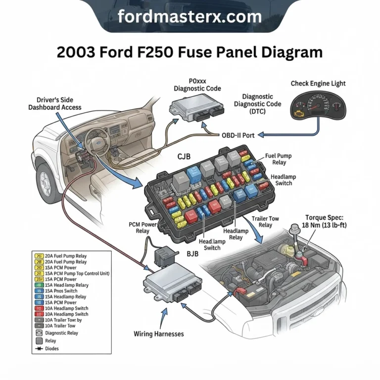
The 2001 Ford Expedition features two primary fuse panels: the passenger compartment panel located under the dashboard to the left of the steering column and the Power Distribution Box in the engine bay. The engine box houses high-amperage relays for the ECU, fuel pump, and blower motor, essential for diagnostic troubleshooting.
📌 Key Takeaways
- The interior panel manages 12V accessories, while the engine bay box controls the PCM, ECU, and primary ignition circuits.
- Always reference the owner’s manual legend, as specific trim levels for the 2001 Expedition vary in relay configuration.
- Ensure the battery is disconnected before performing resistance checks on main power lines to avoid damage.
- A common failure point is the oxidation of the fuel pump relay pins, often mistaken for a faulty ECU or fuel system issue.
- Professional assistance is recommended if the OBD-II port shows no power, as this suggests a deep-seated harness short.
The 2001 Ford Expedition relies on a sophisticated electrical architecture to manage its diverse array of creature comforts and powertrain systems. Navigating the 2001 Ford Expedition fuse box diagram is a fundamental skill for any technician or dedicated DIYer tasked with resolving electrical gremlins. Because this model utilizes a complex network of relay-controlled circuits, misinterpreting the fuse map can lead to unnecessary component replacement. Whether you are addressing an intermittent check engine light or a total loss of cabin power, identifying the correct fuse or relay position within the Power Distribution Center (PDC) and the interior panel is the critical first step in an efficient diagnostic workflow.

Prime for Young Adults — 6 Months Free
Students and 18–24s get six months of Prime free, then half price.
Start 6 Months Free As an Amazon Associate I earn from qualifying purchases.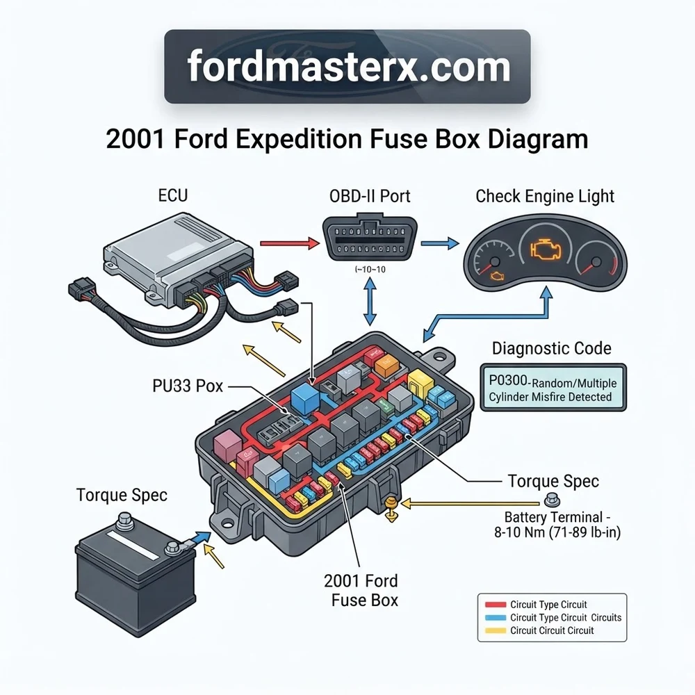
2001 Ford Expedition Fuse Box Diagram: Component Identification
Recommended Best Deal Products


The 2001 Ford Expedition features two primary electrical hubs. The first, the Power Distribution Center (PDC), is located in the engine bay, typically near the driver-side fender well. This center manages high-amperage feeds for the ECU, cooling fans, and fuel pump. The second hub is the interior fuse panel, situated beneath the dashboard on the driver’s side, which regulates secondary electronics, lighting, and convenience features.
Understanding the interaction between these modules is vital. When an ECU fails to receive a signal, the fault often resides in the PDC relay rather than the ECU itself. The following table provides a breakdown of common circuits found within these units.
| Circuit Function | Location | Amp Rating |
|---|---|---|
| PCM / ECU Power | PDC | 30A |
| Fuel Pump Relay | PDC | 20A |
| OBD-II Data Link | Interior Panel | 15A |
| Electronic Shift Control | Interior Panel | 10A |
| A/C Clutch Relay | PDC | 15A |
The layout uses standard blade-style fuses categorized by color coding—typically 10A (Red), 15A (Blue), 20A (Yellow), 25A (Clear), and 30A (Green). When inspecting these, look for continuity across the internal filament. A visual check can be deceptive; high-resistance connections can exist even when the filament appears intact, necessitating a load-test check with a digital multimeter.
Relays in the PDC are equally critical. These electromechanical switches allow the low-current ECU signal to activate high-current loads like the starter solenoid or fuel pump. If you hear a “click” but the device fails to engage, the relay contacts are likely pitted or carbon-fouled, requiring a replacement of the relay unit itself. Always ensure the replacement matches the original OEM part number to avoid back-feeding voltage into sensitive control modules.
Note that the 2001 model year transitioned mid-cycle for some auxiliary modules. If your vehicle features the towing package, the PDC will contain additional relays for trailer battery charge and electric brake control that are absent in non-towing configurations.
Common 2001 Ford Expedition Fuse Box Diagram Issues and Symptoms
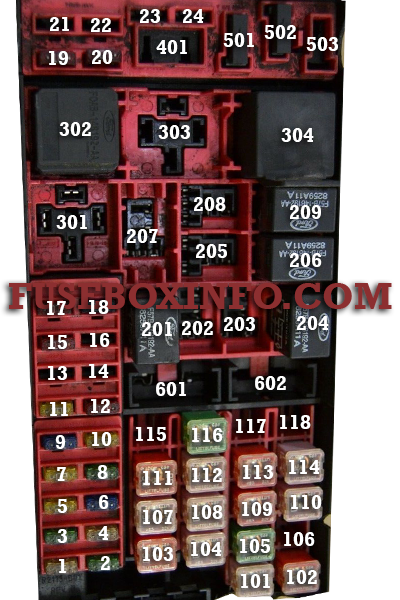
Electrical failures in the 2001 Expedition often masquerade as mechanical issues. A blown fuse on the fuel pump circuit is frequently misdiagnosed as a failed fuel pump or a faulty timing chain tensioner issue, as both result in a no-start condition. Recognizing the symptoms of a fuse or relay failure versus a hardware failure is the hallmark of a skilled technician.
A common issue involves the OBD-II diagnostic port losing power. If your scan tool fails to communicate with the ECU, check the cigarette lighter/auxiliary power fuse. Often, these circuits share a common ground or fuse block, and a shorted accessory can disable the communication port. This prevents you from reading a diagnostic code, effectively blinding you to engine performance issues like misfires or sensor failure.
Voltage drop is another concern. If the fuse box terminals have corroded due to moisture intrusion—common in the engine bay PDC—you may see fluctuating oil pressure gauge readings or intermittent check engine light illumination. This is rarely caused by the sensor itself; instead, it is a sign of poor continuity through the bus bar.
When inspecting the system, pay close attention to the ampere rating. Never substitute a fuse with a higher-rated unit to solve a recurring blow-out. This bypasses the thermal protection and can cause wire insulation to melt, leading to harness fires. A recurring blown fuse is indicative of a short-to-ground in the circuit downstream. Inspect the wiring pigtail at the connector point for signs of chafing, specifically near the steering column or where wire looms pass through the firewall.

Audible — Listen Free for 30 Days
One free credit a month and thousands of titles included.
Listen Free for 30 Days As an Amazon Associate I earn from qualifying purchases.Diagnosis Steps for 2001 Ford Expedition Electrical Circuits
Recommended Best Deal Products


Following a repeatable diagnostic procedure is necessary to isolate electrical faults efficiently. When dealing with complex systems, do not rely on trial-and-error component swapping. Instead, utilize the 2001 Ford Expedition fuse box diagram to map the circuit and test for electrical integrity.
1. Verify Power Supply at the Fuse: Use a digital multimeter (DMM) set to DC voltage. With the key in the “Run” position, touch the black lead to a known clean chassis grounding point and the red lead to the exposed metal tabs on top of the fuse. If you measure battery voltage (approx. 12.6V) on one side but not the other, the fuse is blown.
2. Check for Parasitic Draw: If a fuse continues to blow, set your DMM to the “Amps” function. Remove the fuse and place the multimeter leads in series with the circuit. A high current reading while the vehicle is off indicates a short-to-ground or a stuck relay.
3. Inspect the Grounding Point: Many electrical gremlins are actually bad grounds. Locate the primary ground strap near the battery and the auxiliary grounds behind the kick panels. Clean these with a wire brush to ensure a low-resistance path, as high resistance here can cause strange feedback into the ECU.
4. Test the Pigtail and Connectors: If the fuse is good but the component (e.g., fuel pump) is not working, test for voltage at the component’s pigtail. If you have voltage at the fuse but not at the component, you have a break in the wiring harness. Use a continuity test on the wires to map the fault.
5. Analyze Diagnostic Data: If the vehicle remains in a no-start state, check for a diagnostic code related to the ECU. A P0600 or similar communication error often points back to the PDC relay banks.
Before performing any electrical work, disconnect the negative battery terminal. The 2001 Expedition utilizes sensitive electronics, and accidental shorts during probing can permanently damage the ECU or the anti-theft module.
Beyond the fuse box, be aware of how electrical circuits affect mechanical systems. For instance, cooling fan activation is managed by the PDC relay. If the fan fails to trigger, it may lead to improper coolant flow regulation. While coolant flow is primarily mechanical, the sensor signal processed by the ECU determines when the relay kicks in. Therefore, a faulty relay can lead to an overheating condition. Similarly, ensure that your diagnostic efforts do not ignore mechanical specs; if you are troubleshooting a low oil pressure light, verify the pressure with a mechanical gauge before blaming the electrical sensor circuit.
When reconnecting electrical sensors or relay housings, adhere to the manufacturer torque spec of 8-10 Nm for grounding bolts. Over-tightening can crack the plastic housing of the fuse block, leading to internal moisture accumulation.
2001 Ford Expedition Fuse Box Diagram Questions Answered
Where is the OBD-II port fuse located?
The OBD-II diagnostic link is typically tied to the “Cigar/Auxiliary” fuse located in the interior cabin fuse panel. If you are unable to connect your scan tool to retrieve a diagnostic code, check this specific 15A fuse first.
Can a relay failure cause a check engine light?
Yes. If the relay for the fuel system, O2 sensor heater, or ECU power fails, the lack of signal will trigger a check engine light. Always verify the relay functionality using a multimeter or a known-good spare before suspecting a deeper hardware failure.
What causes the fuse box to smell like burning plastic?
This is a critical sign of a high-resistance connection at the terminal. Oxidation or loose terminals within the fuse block cause heat buildup. If you notice this, you must replace the fuse block or the specific connector pigtail to prevent a fire.
How do I identify a faulty coolant flow sensor circuit?
If the temperature gauge is erratic, check the wiring harness leading from the sensor to the ECU. Inspect the fuse box for any relays labeled “Fan Control.” A faulty relay will cause the engine to overheat due to the fan failing to cycle, despite the sensor being fully functional.
Why does my fuel pump fuse blow immediately?
A short-to-ground is the most common cause. This can occur in the harness where it travels along the frame rail, especially if the insulation has chafed against the chassis. Inspect the entire length of the fuel pump wire harness for exposed copper before replacing the fuse again.
Audible Premium Plus — Annual Membership
12 audiobook credits up front, plus the full Audible catalogue.
See Annual Plans As an Amazon Associate I earn from qualifying purchases.Step-by-Step Guide to Understanding the 2001 Ford Expedition Fuse Box Diagram
Recommended Best Deal Products


Identify – Locate the fuse box cover and verify the specific circuit number related to your malfunction.
Locate – Gain access to the engine bay or cabin panel depending on the suspected circuit area.
Reference – Cross-reference the blown fuse with the diagram to confirm it matches the required amperage rating.
Connect – Use a multimeter to verify voltage at the terminal, ensuring the ECU and other modules are receiving power.
Verify – Clear any existing diagnostic code with an OBD-II scanner after replacing the faulty fuse or relay.
Troubleshoot – If the fuse blows again, inspect the wire harness for shorts to ground before applying further diagnostic pressure.