
Ford 5.4 Heater Hose Diagram: 2026 Routing & Maintenance Guide

The 5.4L Triton engine utilizes a dual-hose configuration connecting the intake manifold water outlet and the engine block to the heater core inlet/outlet. The supply hose routes coolant from the intake crossover, while the return hose connects the heater core to the water pump bypass tube near the firewall.
📌 Key Takeaways
- The supply hose typically features a 5/8-inch inner diameter, while the return line often requires 3/4-inch sizing.
- Always identify the flow direction; the intake manifold port serves as the high-pressure side feeding the heater core.
- Verify quick-connect fittings are seated until an audible click is heard to prevent high-pressure coolant leaks.
- The most common failure point is the plastic quick-connect coupling, which becomes brittle and leaks due to engine heat cycles.
- Professional assistance is recommended if the heater core itself is clogged, as it requires extensive dashboard disassembly.
Maintaining the thermal efficiency of the Ford 5.4L Triton engine requires a precise understanding of the coolant circulation path. When HVAC performance degrades or coolant puddles appear under the firewall, referring to a technical Ford 5.4 heater hose diagram becomes essential. These hoses are engineered to withstand high-pressure, high-temperature fluctuations; however, the reliance on proprietary quick-connect fittings and complex routing means that a standard “one-size-fits-all” hose will inevitably fail. By analyzing the structural configuration of your specific vehicle’s cooling system, you can avoid diagnostic errors, prevent engine overheating, and ensure the heater core receives the consistent flow necessary for both cabin comfort and reliable thermal management.
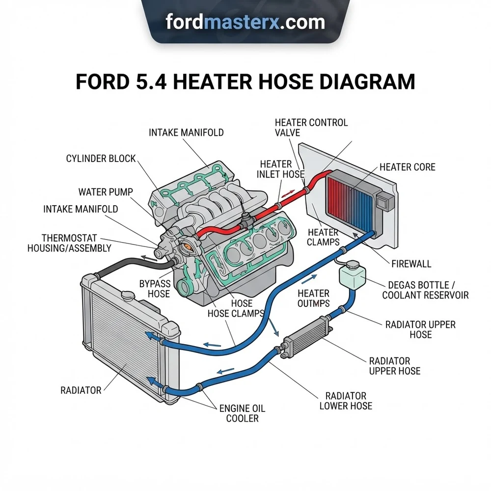
Ford 5.4 Heater Hose Diagram: Component Breakdown and Layout


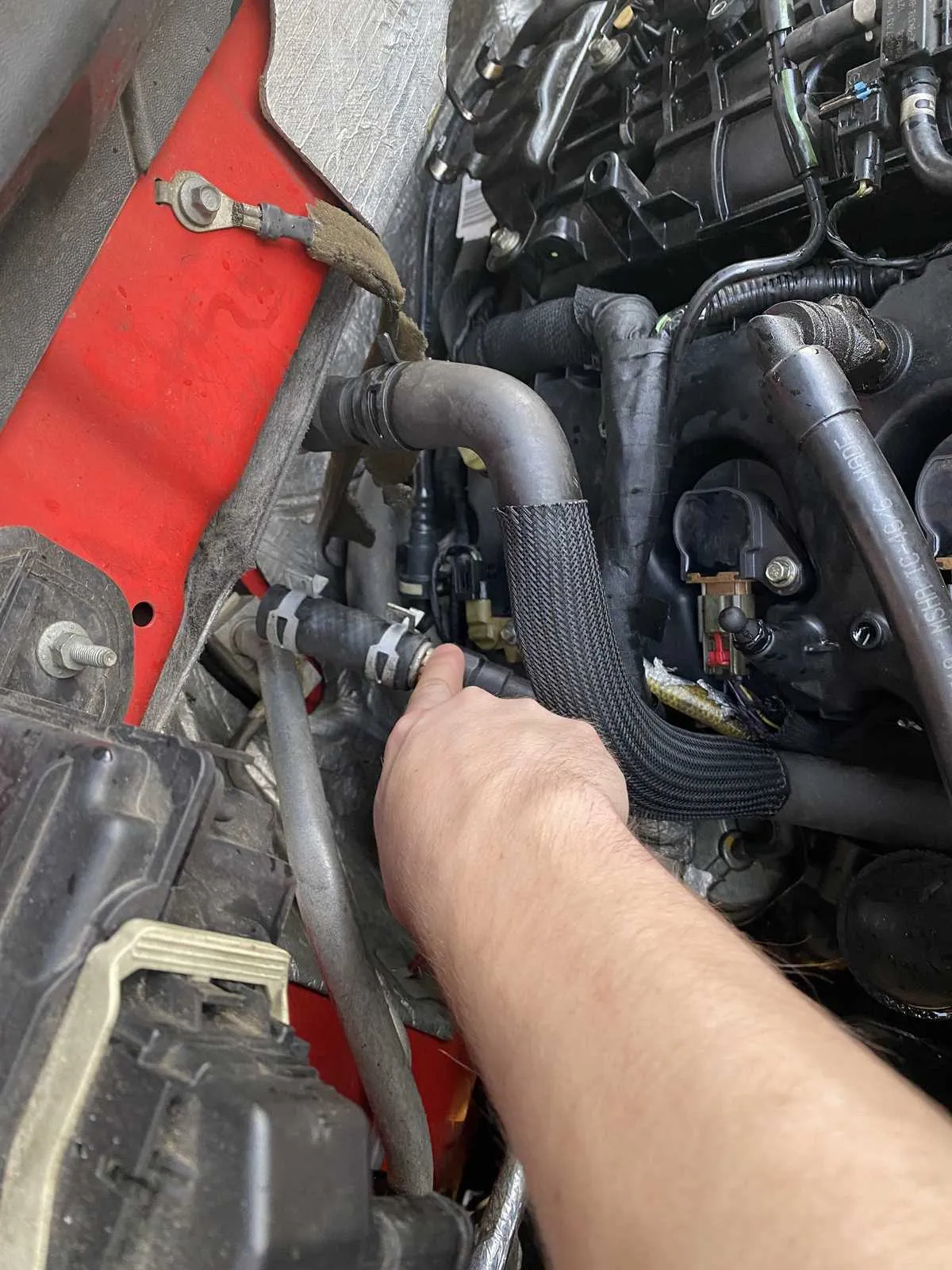
To effectively navigate the cooling system, technicians must distinguish between the supply and return lines within the Ford 5.4 heater hose diagram. The supply hose, typically connected to the intake manifold or the thermostat housing, carries hot engine coolant directly to the heater core. The return hose then routes the cooled fluid back to the suction side of the water pump. Misidentifying these lines during replacement or auxiliary component installation can result in air pockets that prevent the heater core from venting properly, leading to an air-bound system that produces only cold air despite a fully warmed engine.
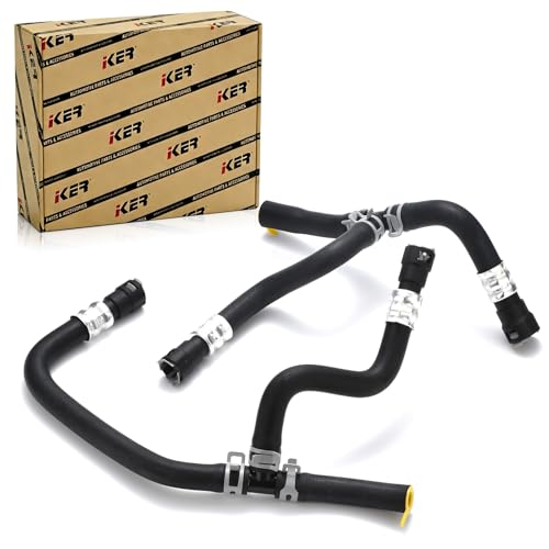


The system relies on several critical junctions to maintain fluid pressure. You will encounter quick-connect fittings, which are notorious for failing at the O-ring seals after high-mileage service. These plastic connectors must be handled with specialized release tools to avoid cracking the mating surfaces on the heater core pipes.
| Component | Function | Technical Specification |
|---|---|---|
| Heater Supply Hose | Transfers hot coolant to core | 5/8 inch ID reinforced EPDM |
| Heater Return Hose | Returns coolant to water pump | 3/4 inch ID reinforced EPDM |
| Quick-Connect Fitting | Structural hose-to-core coupling | Nylon composite with Viton O-ring |
| Heater Control Valve | Regulates flow (Vacuum/Electric) | Normally open; vacuum-actuated |
When examining the layout, pay close attention to the T-connectors present in later-model F-150 and Expedition platforms. These are often used to bleed air or accommodate additional climate control zones. If you observe swelling in the rubber, it indicates internal degradation; even if the hose holds pressure today, the structural integrity is compromised. Always verify the routing against the manufacturer’s blueprint to ensure no kinks are present, as a restricted flow here directly impacts the thermal load on the cylinder heads.
Understanding the Ford 5.4 Cooling System Architecture
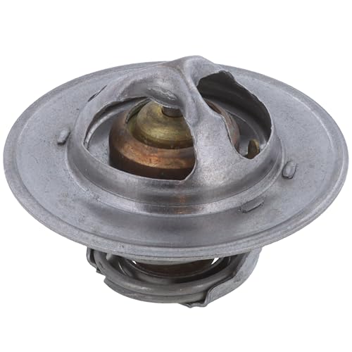


The Ford 5.4L Triton engine utilizes a complex cooling circuit that differs significantly between the 2V (two-valve) and 3V (three-valve) platforms. In the 2V configuration, the heater hoses are generally straightforward, routing from the intake manifold to the firewall. However, the 3V engines—notably those in the 2004–2008 F-series—feature more intricate cooling paths to manage the heat generated by the variable valve timing (VVT) components. The thermal expansion of the aluminum heads requires a cooling system that responds dynamically, which is why the heater hose diagram includes specific dampeners and flow regulators to prevent pressure spikes during cold starts.
When servicing the 3V Triton engine, always verify your coolant level using a vacuum-fill tool. The complex internal passages make the 5.4L highly prone to trapped air pockets, which can mimic the symptoms of a failed heater core or a stuck thermostat.
The thermostat housing acts as the primary synchronization point for the entire cooling system. The architecture is designed to allow bypass circulation even when the thermostat is closed; this ensures the heater core remains warm during the warm-up cycle. If your system is failing to provide heat, look at the thermostat housing connection in your Ford 5.4 heater hose diagram; a faulty thermostat often causes the heater core to receive lukewarm coolant instead of full engine-temp fluid, leading to an uneven heat gradient across the HVAC distribution box.
How to Replace Ford 5.4 Heater Hoses Step-by-Step


Replacing these hoses requires more than just a screwdriver. Because the Triton engine bay is tightly packed, you must prioritize workspace clearance. Begin by draining the cooling system to a level below the heater core entry points—typically removing about two gallons of coolant from the radiator petcock is sufficient.


1. Depressurize and Drain: Ensure the engine is completely cool. Use a vacuum-style coolant exchanger if available, or drain the radiator to prevent spills during the hose disconnection process.
2. Access the Quick-Connects: Use a professional-grade plastic quick-connect release tool. Do not attempt to pry these with a flat-head screwdriver, as the plastic tabs are brittle and the heater core pipes are often corroded, making them susceptible to bending.
3. Inspect the Heater Core Ports: Once the hoses are removed, inspect the copper or aluminum ports on the core for pitting or residue. If the surface is rough, you must polish it with fine-grit emery cloth to ensure a perfect seal for the new O-rings.
4. Install New Hoses: Lubricate the new O-rings with clean engine coolant. Align the hoses exactly as shown in your Ford 5.4 heater hose diagram. Improper orientation will lead to premature fatigue at the connection point.
5. Bleed the System: With the hoses secured, refill the system using the proper Motorcraft coolant specification. Start the engine and set the climate control to max heat. Monitor the temperature gauge closely. Use the radiator’s air-bleed screw (if equipped) to vent trapped air until a steady stream of coolant appears.
Do not use universal silicone hoses for the high-pressure runs. The 5.4L engine operates at higher pressures than many automotive systems. Always use SAE J20R3 or J20R4 rated coolant hoses to prevent catastrophic bursting under heavy load.
Common Ford 5.4 Heater Hose Diagram Issues and Fixes
Identifying the root cause of a heating system failure requires a methodical approach. Often, the diagram reveals that the issue is not the hose itself, but a peripheral component interacting with the coolant flow.
Coolant T-Connector Leaks: The plastic T-connectors located in the return lines often develop hairline cracks. Symptoms include a sweet smell of coolant in the cabin or minor seepage onto the passenger-side floor mat. Replacement with high-quality metal T-fittings is the recommended permanent fix.
HVAC Blend Door Actuator Failure: If your hoses are hot to the touch but the cabin air remains cold, the issue is not in the hoses but in the HVAC plenum. The blend door actuator often fails in a position that blocks airflow through the heater core.
Heater Core Inlet Obstruction: If the supply hose is hot but the return hose remains cool, this indicates a lack of flow through the heater core. This is frequently caused by casting sand or debris trapped in the core inlet.
Vacuum Actuated Valve Failure: In models equipped with a heater control valve, a loss of vacuum will cause the valve to stay closed. Check the vacuum line integrity running from the intake manifold to the valve; a cracked rubber line is a common, low-cost fix that mimics a major cooling system failure.


Coolant System Capacity: 18-20 Quarts (varies by model/towing package). Use only Motorcraft Gold or specialized extended-life coolant meeting Ford specification WSS-M97B51-A1.
Ford 5.4 Heater Hose Diagram Questions Answered
Is it necessary to replace the heater core when replacing the heater hoses?
Not necessarily, but it is standard practice to inspect the heater core’s inlet tubes for corrosion when the hoses are removed. If you notice heavy pitting, it is safer to replace the core, as the new hoses will not seal properly against a degraded metal surface.
Why does my heater hose diagram show a tee connector when some models do not?


The inclusion of T-connectors usually denotes a vehicle equipped with a heavy-duty cooling package or an auxiliary rear climate control system. Always match the diagram to your VIN, as the cooling configuration can vary between 150, 250, and expedition-based chassis.
What is the torque spec for heater hose clamps on the 5.4L?


While most connections on the 5.4L use quick-connects, any auxiliary clamps should be tightened to 20–25 inch-pounds. Over-tightening can easily crush the heater core pipe or cause the hose to deform, leading to immediate leaks.


Can I bypass the heater core if it is leaking?


You can temporarily loop the supply and return hoses together using a suitable barbed coupling to bypass the core in an emergency. However, do not leave this in place long-term, as it alters the coolant flow rate and can negatively impact the engine’s overall thermal efficiency.
How do I confirm the heater core is clear after flushing?


After back-flushing the heater core, the flow rate should be essentially unobstructed. If you observe significant resistance or back-pressure when flushing, the core is internally clogged with scale and requires replacement to restore proper cabin heat.