2.3 EcoBoost Ford Engine Diagram: Component Breakdown (2026)

The 2.3L EcoBoost features a DOHC 16-valve architecture with a twin-scroll turbocharger. Key components include the direct-injection fuel system, variable camshaft timing (VCT) actuators, and a forged steel crankshaft. The engine utilizes a chain-driven valve train; maintenance requires precise timing alignment using specialized Ford tool kit 303-1521 to ensure correct synchronization.
📌 Key Takeaways
- The 2.3 EcoBoost utilizes a high-pressure fuel pump (HPFP) driven by a dedicated lobe on the intake camshaft.
- Engine identification is verified via the laser-etched serial number located on the block flange near the transmission bell housing.
- Cylinder head bolts are torque-to-yield (TTY) and must be replaced; final torque sequence is 30Nm, 50Nm, plus 90 degrees.
- The most frequent failure involves coolant intrusion into the combustion chamber due to head gasket fatigue or block deck erosion.
- DIY repairs on the timing assembly require professional-grade locking tools; improper alignment leads to catastrophic valve-to-piston interference.
The Ford 2.3 EcoBoost engine represents a sophisticated marriage of high-pressure direct injection, twin-scroll turbocharging, and variable valve timing. For technicians and advanced enthusiasts, understanding the architecture within a comprehensive Ford 2.3 EcoBoost engine diagram is paramount to diagnostic success. This platform relies on a closed-deck engine block design capable of handling high cylinder pressures, necessitating a deep familiarity with the internal reciprocating assembly and the integration of auxiliary forced-induction systems. Whether you are performing a timing chain service or diagnosing a boost leak, mapping the interaction between the cylinder head, the high-pressure fuel system, and the electronic management components is essential for maintaining optimal power delivery and long-term engine durability.

Prime for Young Adults — 6 Months Free
Students and 18–24s get six months of Prime free, then half price.
Start 6 Months Free As an Amazon Associate I earn from qualifying purchases.
Ford 2.3 EcoBoost Engine Diagram: Component Identification and Layout
Recommended Best Deal Products


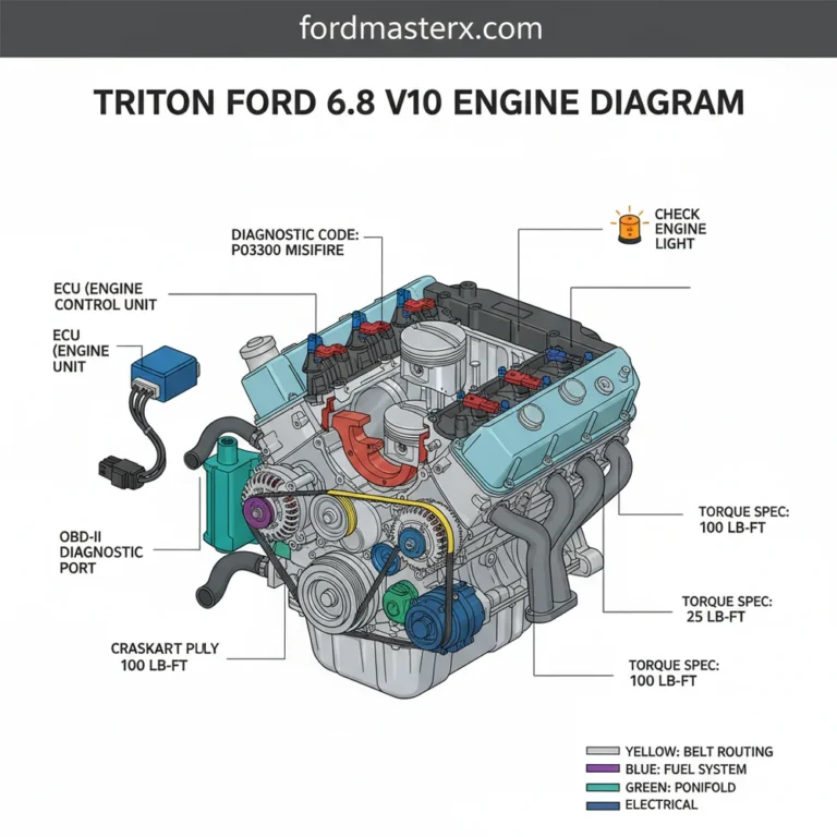
To interpret the Ford 2.3 EcoBoost engine diagram effectively, one must categorize the powerplant into its primary sub-assemblies. At the core, the engine block features an open-deck or closed-deck geometry depending on the specific model year, providing the housing for the forged connecting rods and aluminum-alloy pistons. The reciprocating mass is connected to a hardened steel crankshaft that utilizes high-tolerance main bearings to manage the substantial torque output typical of this forced-induction platform. Referencing the diagram, the crankshaft position sensor (CKP) is located near the harmonic balancer, providing the signal necessary for the powertrain control module (PCM) to synchronize ignition timing.
The cylinder head serves as the command center for combustion efficiency, housing the dual overhead camshafts (DOHC). The intake and exhaust camshafts utilize Variable Camshaft Timing (Ti-VCT) phasers, which adjust valve overlap to optimize volumetric efficiency across the RPM range. The valve train is a direct-acting mechanical bucket design, requiring precision when performing valve lash adjustments. If the diagram indicates excessive wear on the cam lobes, it often correlates with a failure in the high-pressure fuel pump (HPFP) follower, as the HPFP is driven directly by a lobe on the exhaust camshaft. Inspecting the HPFP mounting point on the cylinder head cover is a frequent requirement during scheduled maintenance.
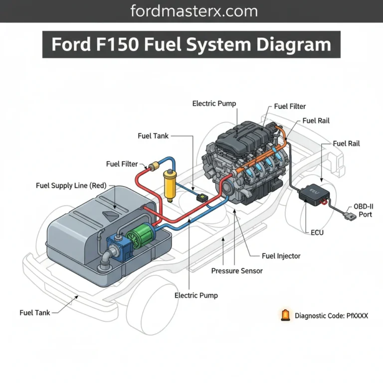
The forced induction system integrated into this layout is centered around the twin-scroll turbocharger. The diagram illustrates how exhaust pulses from cylinders 1-4 are partitioned to minimize turbine lag and maximize low-end torque. The intake manifold design incorporates an integrated charge air cooler (for specific transverse applications) or feeds into a front-mounted intercooler. The high-pressure direct fuel injectors are seated directly into the combustion chamber through the cylinder head, operating at pressures exceeding 2,000 PSI under load. When analyzing the fuel delivery path in the diagram, ensure the fuel rail pressure sensor and the injector wiring harnesses are routed clear of the high-heat zones near the exhaust manifold to prevent insulation degradation.
When referencing the timing marks in the engine diagram, ensure the crankshaft is at Top Dead Center (TDC) for cylinder #1. The Ti-VCT phasers must be locked using specialized Ford service tools (303-1565 or equivalent) to prevent internal synchronization errors that could lead to valve-to-piston contact.
Ford 2.3 EcoBoost Engine Diagram: Generations and Variants
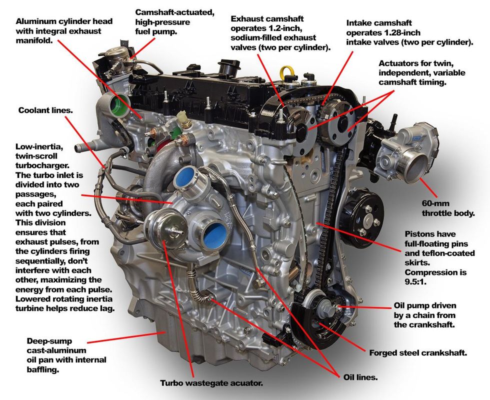
The versatility of the 2.3 EcoBoost engine has resulted in several hardware configurations across Ford’s product line. Identifying your specific generation is critical when using an engine diagram, as oil pan designs, accessory drive layouts, and vacuum line routing differ significantly between longitudinal (RWD) and transverse (FWD/AWD) orientations.
| Vehicle Model | Orientation | Engine Block Code |
|---|---|---|
| Ford Mustang (2015+) | Longitudinal | 2.3L I4 GTDI |
| Ford Focus RS (2016-2018) | Transverse | 2.3L High Output |
| Ford Explorer (2020+) | Longitudinal | 2.3L Twin-Scroll |
| Lincoln Corsair (2020+) | Transverse | 2.3L I4 GTDI |
The transverse layout found in the Focus RS features a distinct turbocharger location and exhaust downpipe routing, which drastically changes the accessibility of the oil pan and oil cooler components compared to the Mustang’s longitudinal layout. Technicians must be aware that while the internal components—such as the connecting rod and piston specifications—remain largely identical in architecture, the engine block casting details may vary to accommodate different transmission bellhousing patterns and mounting points for AWD transfer cases.
Furthermore, the cooling system layout in the Ford 2.3 EcoBoost engine diagram varies by generation. Later models, such as the 2020+ Explorer, feature enhanced thermal management systems, including electric coolant pumps and more complex heat exchanger networks. Failure to utilize the correct diagram for your specific model year can result in incorrect routing of vacuum lines for the bypass valve, leading to under-boost conditions or erratic engine behavior.
Common Ford 2.3 EcoBoost Engine Diagram Failure Points
Recommended Best Deal Products

Effective troubleshooting begins with analyzing the components identified in your Ford 2.3 EcoBoost engine diagram that are prone to thermal fatigue or mechanical wear. Many diagnostic procedures rely on tracing vacuum lines and electrical signals from sensors that are often obscured by the engine cover or air induction plumbing.
- Charge Air Cooler (Intercooler) Leaks: As illustrated in the intake path of the diagram, the intercooler is a high-pressure component. Plastic end-tanks often develop hairline fractures, leading to a loss of boost pressure and triggering P0299 under-boost diagnostic trouble codes (DTCs).
- Boost Solenoid Malfunction: The boost control solenoid is tasked with modulating the wastegate actuator. If the diagram shows a blockage or a pinched vacuum line, the turbocharger may over-boost, causing the PCM to enter “limp home” mode to protect the engine block from internal damage.
- Oil Pan and Gasket Seepage: The oil pan seal is a recurring point of failure in high-mileage units. Because the pan is structural on many variants, improper torque sequencing during re-installation can lead to chronic leaks. Always consult the diagram for the specific bolt-tightening pattern, which is usually a center-outwards cross pattern to ensure even gasket compression.
- Blow-off Valve (BOV) Diaphragm Failure: Located on the compressor housing, the BOV controls charge pressure release. A ruptured diaphragm prevents the turbo from maintaining consistent boost levels during gear shifts, which is clearly visible in the turbo-bypass loop of the factory diagram.
- Dual-Mass Flywheel Fatigue: While not part of the internal rotating assembly, the flywheel is depicted as the connection point to the transmission. Excessive vibration or rattling at idle is a signature symptom of internal spring fatigue within the dual-mass assembly.
Never attempt to loosen the crankshaft pulley bolt without securing the crankshaft position with a factory-specified locking tool. The 2.3 EcoBoost uses a friction-washer design; reusing the original torque-to-yield bolt can result in pulley slippage and catastrophic engine timing failure.

Audible — Listen Free for 30 Days
One free credit a month and thousands of titles included.
Listen Free for 30 Days As an Amazon Associate I earn from qualifying purchases.Frequently Asked Questions About the 2.3 EcoBoost
How often should the valve train be inspected for wear?
The valve train, specifically the tappets and camshaft followers, should be inspected during every major timing chain service, typically recommended at 100,000 to 150,000 miles. Signs of excessive ticking or performance degradation may indicate a need for a premature inspection of the cylinder head components.
Can the internal connecting rod be replaced without removing the engine block?
Technically, the oil pan and cylinder head can be removed with the engine in the chassis, allowing for the extraction of a piston and connecting rod. However, this is highly discouraged for precision assembly. Most professional shops recommend a full engine removal to ensure proper main and rod bearing clearance measurements using plastigauge.
Where is the crankshaft position sensor located on the engine diagram?
The crankshaft position sensor (CKP) is located on the lower engine block, typically on the passenger side or rear, positioned to read the reluctor wheel on the crankshaft. Refer to your specific chassis diagram, as clearance varies significantly between FWD and RWD engine configurations.
What does a P0300 code indicate on this engine?
A P0300 code indicates a random or multiple cylinder misfire. On the 2.3 EcoBoost, this is often caused by carbon buildup on the intake valves—a common byproduct of direct injection—or a failure in the ignition coil pack. Consult the engine diagram to verify the firing order (1-3-4-2) and check the individual ignition coils for signs of heat stress.
For the 2.3 EcoBoost, the standard engine oil capacity is approximately 5.7 quarts (5.4 liters) including the filter. Always use full-synthetic 5W-30 oil meeting Ford WSS-M2C946-A specifications to protect the turbocharger bearings and internal valve train components from premature sludge formation.
Step-by-Step Guide to Understanding the Ford 2.3 Ecoboost Engine Diagram
Identify – Locate the engine identification tag on the lower engine block near the transmission mating surface.
Locate – Cross-reference the serial number with the 2026 model year guide to confirm your specific engine variant.
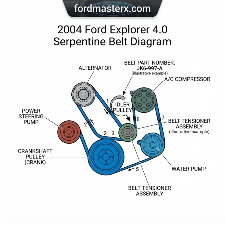
Reference – Use the engine diagram to trace the routing of the serpentine belt and cooling system lines.
Connect/Route – Secure all sensor harnesses, ensuring the camshaft position sensor is clicked fully into its retention clip.
Torque – Tighten all primary fasteners, such as the cylinder head bolts, using a calibrated digital torque wrench to factory specifications.
Audible Premium Plus — Annual Membership
12 audiobook credits up front, plus the full Audible catalogue.
See Annual Plans As an Amazon Associate I earn from qualifying purchases.Troubleshoot – Perform a leak-down test if the engine exhibits rough idling to verify the integrity of the valves and rings.