
2016 F150 Fuse Box Diagram: 2026 Troubleshooting Guide

The 2016 F150 features two main power distribution boxes: the Battery Junction Box (BJB) under the hood and the Body Control Module (BCM) in the passenger footwell. Refer to the interior lid mapping for specific circuit assignments. Always verify the current rating before replacing any fuse to avoid damaging the ECU or wiring.
📌 Key Takeaways
- Always use the correct amperage-rated fuse; installing a higher rating can cause permanent harness damage.
- The BJB contains high-current mega fuses secured with 10mm bolts requiring 8Nm torque specification.
- Check OBD-II port connectivity before replacing BCM fuses if the scanner fails to link to the ECU.
- Persistent check engine light issues often trace back to corroded relay pins rather than blown fuses.
- Professional diagnosis is required if the BCM exhibits internal board failure, as programming is necessary for replacement.
Maintaining the complex electrical architecture of a 2016 Ford F-150 requires a precise understanding of power distribution. As modern vehicles become more reliant on integrated modules, the 2016 F150 fuse box diagram serves as the primary roadmap for any technician tasked with diagnosing intermittent power failures, ECU communication errors, or failed sensor circuits. Whether you are investigating an illuminated check engine light or addressing a persistent parasitic drain, identifying the correct circuit path is essential for preserving the integrity of the vehicle’s CAN-bus network and preventing collateral damage to sensitive electronic control modules.
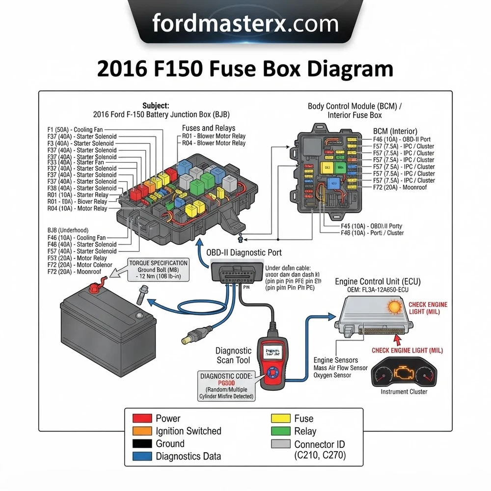
Locating Every 2016 F150 Fuse Box Diagram Panel

The 2016 Ford F-150 utilizes a sophisticated dual-junction architecture to manage high-amperage demands and low-voltage signal distribution. Mastering the 2016 F150 fuse box diagram requires first identifying the specific physical locations of these power centers, as misidentifying a relay or fuse can lead to incorrect diagnostic conclusions during electrical testing.


The Battery Junction Box (BJB) Architecture

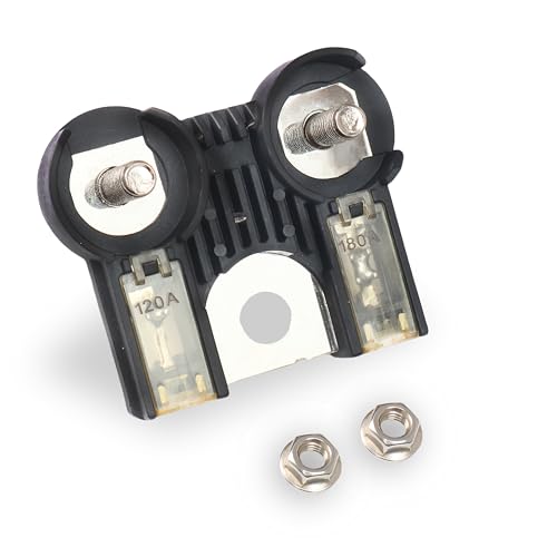
The primary power distribution center, often referred to as the Battery Junction Box, is housed within the engine bay. To access this panel, you must unlatch the primary plastic cover located on the passenger side near the firewall. This BJB handles high-amperage circuits that manage heavy-duty operations such as the starter solenoid, fuel pump motor, and anti-lock brake system (ABS) actuators. It is here that you will find the main high-current J-Case fuses that protect critical power supply lines from the alternator and battery. Always verify the orientation of the cover, as the underside often contains a supplemental quick-reference guide specific to your trim package.
The Passenger Junction Box (PJB) and Interior Modules


The secondary fuse panel is located within the passenger cabin, situated behind the kick panel on the passenger side floor. This module facilitates lower-amperage distribution for cabin convenience features, interior lighting, and data bus gateways. Accessing the PJB requires removing the trim panel; however, ensure the ignition is in the OFF position before manipulating any connectors. The PJB is closely linked to the body control module (BCM), which manages the signal distribution for the vehicle’s convenience systems. If you notice interior accessory failures but the engine bay fuses remain intact, focus your testing here.
When referencing the Ford Owner Manual for your specific trim, note that mid-year production changes may alter fuse assignments for auxiliary upfitter switches or trailer tow packages. Always cross-reference the diagram on the physical cover with the VIN-specific digital manual.
2016 F150 Fuse Box Diagram: Component Identification


The 2016 F150 fuse box diagram represents a complex matrix of protection devices designed to prevent thermal runaway. Understanding the distinction between blade fuses, J-Case fuses, and relays is fundamental for accurate circuit analysis. The following table identifies the common component types found within the engine and cabin junction boxes.
| Component Type | Typical Function | Service Protocol |
|---|---|---|
| Mini/Micro Blade Fuse | Low current interior/sensor logic | Visual inspection for filament gap |
| J-Case Fuse | High current engine/ABS/BJB main | Requires needle-nose or fuse puller |
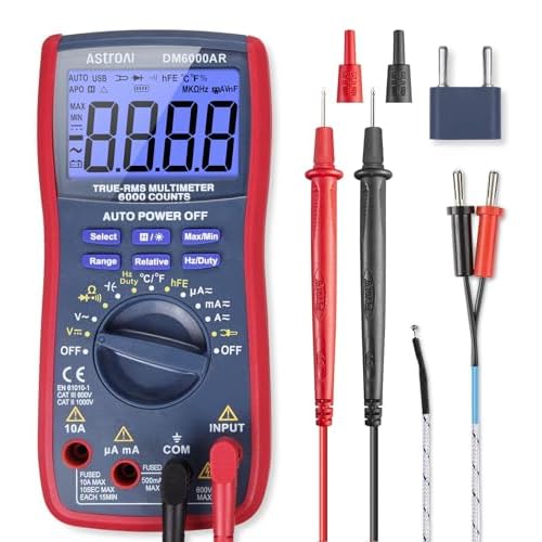
| Micro/Mini Relay | High-load circuit switching | Test coil resistance via multimeter |
| Ford Fuse Puller | Tool for extraction | Store in BJB or glove compartment |
Every relay within the box serves as an electromagnetic switch, allowing a low-amperage signal from the ECU to control high-amperage devices like cooling fans or headlamps. If a device fails to activate, the fault may lie not in the fuse, but in the relay contacts which can become pitted over high-mileage duty cycles.
Common 2016 F150 Fuse Box Diagram Issues and Symptoms


Electrical failures in this vehicle platform often present as cascading issues. When a circuit experiences a short to ground, the corresponding fuse is designed to sacrifice itself to protect the wiring harness from melting. Identifying the root cause requires more than just swapping the fuse; it demands an analysis of amperage draw.
- Intermittent ECU Reset: Often linked to loose pins within the main fuse block or corroded power distribution leads near the battery terminals.
- Failed Cooling Fan Actuation: Frequently caused by high-amperage relay failures within the BJB. This can indirectly lead to overheating and potential damage to the timing chain or coolant flow components.
- Unexplained Diagnostic Codes: A blown fuse supplying power to an O2 sensor or mass airflow sensor will immediately trigger a check engine light and a stored diagnostic code in the powertrain control module.
- Parasitic Battery Draw: Often originating from a relay that is stuck in the closed position, keeping a module “awake” long after the ignition is turned off.
Never replace a blown fuse with a higher amperage rating than specified. Doing so can cause wire insulation failure, electrical fire, or irreversible damage to the ECU. Always verify the circuit load before attempting a repair.
Diagnosis Steps for 2016 F150 Electrical Systems
A methodical approach to troubleshooting electrical systems ensures that you do not waste time replacing functional parts. Follow these standardized diagnostic steps to isolate circuit faults efficiently.
- Scan for Diagnostic Trouble Codes: Connect an OBD-II scanner to the vehicle’s diagnostic port. Identify any codes related to voltage, such as P0562 (System Voltage Low) or specific circuit-high/circuit-low codes. These codes narrow the focus of your 2016 F150 fuse box diagram inspection.
- Verify Continuity at the Fuse Terminals: With the ignition OFF and the fuse removed, use a digital multimeter (DMM) set to the continuity/ohms setting. Place probes on both terminals of the fuse. A “beep” or a reading near zero ohms confirms the fuse is intact. If the meter shows “OL,” the fuse is open and must be replaced.
- Execute Voltage Drop Testing: If a fuse is intact but the component it powers is not working, check the voltage at the load side of the fuse socket while the circuit is “live.” A significant drop from the source voltage (typically 12.6V on a healthy battery) indicates a high-resistance connection at the fuse panel itself.
- Inspect ECU Power Feeds: Ensure the ECU is receiving proper ground and battery voltage. A common point of failure is the ground connection located near the engine block or chassis, which can interfere with sensors monitoring oil pressure or intake air temperature.
- Confirm Proper Torque Specs: If you must remove the main BJB for deeper inspection, ensure that all mounting bolts and ground straps are reinstalled to factory torque specs. Loose grounding points create the most erratic, phantom electrical issues.
For critical ground connections on the 2016 F150 chassis, maintain a torque spec of 12-15 Nm (approx. 9-11 lb-ft) to ensure low resistance and prevent oxidation of the terminal surfaces.
2016 F150 Fuse Box Diagram Questions Answered
Can I use an OBD-II scanner to identify a blown fuse?
While an OBD-II scanner cannot directly “see” a blown fuse, it identifies the symptom of the failure. For example, if your check engine light is illuminated due to an open circuit in the fuel injection system, the scanner will provide the code necessary to trace that specific circuit back to the fuse box diagram.


What if the fuse blows immediately after replacement?


This is a classic sign of a hard short to ground. Do not replace it again until you have isolated the wire harness from the component. Check for chafed wires, especially near the timing chain cover or areas where harnesses pass through the firewall, as these are common high-vibration zones.


How does the fuse box affect oil pressure sensor readings?
The oil pressure sensor requires a steady 5V reference signal provided by the ECU. If the fuse supplying the ECU or the sensor bank is compromised, you may receive false “low oil pressure” warnings on your dashboard, even if mechanical oil pressure is within spec.
Is the 2016 F150 fuse box prone to moisture damage?


The Battery Junction Box cover is weather-sealed, but seals can degrade over time. If you live in high-humidity or salt-heavy climates, inspect the connectors for signs of green corrosion. Corroded pins increase resistance and can cause a voltage drop that mimics a failing electronic component.
By approaching the electrical architecture with a focus on systematic testing rather than component swapping, you can effectively resolve even the most elusive issues in your 2016 F-150. Always consult the specific wiring diagrams in the Ford service manual to ensure your diagnostic probes are placed correctly, protecting both the vehicle’s modules and your own equipment from damage.


Step-by-Step Guide to Understanding the 2016 F150 Fuse Box Diagram
Identify – Locate the specific fuse box (under hood or passenger kick panel) using the owner’s manual index.
Locate – Remove the plastic cover by depressing the tabs and cross-reference the diagram layout with the physical slot orientation.
Reference – Use a scan tool to pull diagnostic code data to narrow down which electrical system is failing.
Connect/Route – Inspect the wiring harness underneath the box for signs of heat damage or poor ground connections.
Verify – Insert a new fuse of the identical amperage, ensure it seats firmly, and clear the ECU memory.
Troubleshoot – If the fuse blows again immediately, use a multimeter to check for a short to ground in the affected circuit path.