2011 Ford Fusion Serpentine Belt Diagram: Routing & Maintenance 2026

The 2011 Ford Fusion serpentine belt routing path wraps around the crankshaft pulley, A/C compressor, alternator, and water pump, guided by the belt tensioner and idler pulley. Ensure the grooved side of the belt aligns with the pulley grooves and the smooth side contacts the idler pulley for proper operation.
📌 Key Takeaways
- Use OEM Part Number JK6-870 or equivalent 6-rib belt for the 2.5L 4-cylinder engine.
- Always verify the belt is seated centrally in the pulleys to prevent premature wear or fraying.
- The automatic belt tensioner requires a 15mm or 3/8-inch drive tool to rotate and release tension.
- Ensure the engine is completely cool before attempting belt replacement to avoid contact with hot metal components.
- A squealing noise upon startup often indicates a worn belt or a seized idler pulley bearing, necessitating immediate inspection.
Maintaining the integrity of the accessory drive system on a 2011 Ford Fusion is a critical service procedure that demands strict adherence to manufacturer specifications. Whether you are addressing an aging belt exhibiting signs of rib cracking or replacing a failed tensioner assembly, relying on an accurate 2011 Ford Fusion serpentine belt diagram is essential to ensure correct pulley orientation and optimal deck engagement. This vehicle utilizes distinct routing configurations based on the displacement and cylinder count of the engine, making it imperative to verify your specific power plant before initiating any removal. Misalignment or incorrect routing will lead to catastrophic belt failure, damage to driven accessories, and potential engine overheating.

Prime for Young Adults — 6 Months Free
Students and 18–24s get six months of Prime free, then half price.
Start 6 Months Free As an Amazon Associate I earn from qualifying purchases.Note: Always cross-reference the routing path depicted above with the specific emission label located on the vehicle’s radiator support or engine shroud.
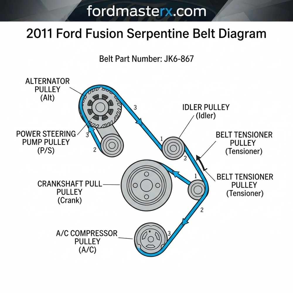
Understanding the 2011 Ford Fusion Serpentine Belt Diagram for Engine Configurations
Recommended Best Deal Products



The 2011 Ford Fusion was produced with three primary engine variations: the 2.5L Duratec I4, the 3.0L Duratec V6, and the 3.5L V6 found in the Sport trim. Each configuration requires a unique belt routing path due to the differing accessory locations and pulley diameters.
Routing Path for the 2.5L I4 Duratec Engine

The 2.5L four-cylinder engine employs a single serpentine belt to drive the alternator, water pump, and air conditioning compressor. The belt routing path is relatively linear, yet it demands precise tensioner engagement. The tensioner is located on the passenger side of the block. When consulting the 2011 Ford Fusion serpentine belt diagram for this unit, note that the belt must pass over the idler pulley before looping under the A/C compressor. Failure to seat the ribs correctly into the water pump pulley grooves often results in premature harmonic balancer vibrations.
Routing Path for the 3.0L and 3.5L V6 Engine Assemblies
V6 configurations are notably more complex. These engines utilize an auxiliary drive system that necessitates careful management of the belt tensioner to clear the frame rail during installation. The 3.0L engine utilizes a specific routing sequence that wraps the belt around the power steering pump, which is absent in the 2.5L setup. In the 3.5L Sport model, the increased accessory load requires a more robust OEM belt with reinforced tensile cords. When viewing the diagram for these V6 units, verify the clearance between the belt and the tensioner body to prevent “deck engagement” interference where the smooth side of the belt contacts a grooved pulley by mistake.
Always inspect the alignment of the alternator pulley during belt replacement. A seized alternator decoupler pulley is the leading cause of premature belt snapping on the Duratec V6 platforms.
2011 Ford Fusion Serpentine Belt Part Numbers and Specifications
Sourcing the correct components is non-negotiable for high-mileage repairs. Using an aftermarket belt of incorrect length will result in the belt tensioner operating outside of its indexed range, leading to rapid bearing fatigue in the idler pulley and alternator.
| Engine Type | Application | OEM Part Number | Effective Length |
|---|---|---|---|
| 2.5L I4 | Main Drive | BE5Z-8620-A | ~2100mm |
| 3.0L V6 | Main Drive | 7G1Z-8620-A | ~2350mm |
| 3.5L V6 | Main Drive | 7T4Z-8620-A | ~2400mm |
When sourcing, prioritize EPDM (Ethylene Propylene Diene Monomer) construction. Unlike older neoprene belts, EPDM belts do not exhibit “cracking” as they wear, meaning visual inspection is often insufficient. Measure belt stretch against the original OEM belt specifications to determine if a tensioner replacement is also required.
How to Read the 2011 Ford Fusion Serpentine Belt Diagram Step by Step
Recommended Best Deal Products


Interpreting the 2011 Ford Fusion serpentine belt diagram requires identifying the “fixed” pulleys versus the “tensioned” pulleys. The diagram acts as your master guide, but the physical application relies on mechanical leverage and proper tool selection.
1. Preparation and Tool Selection: Utilize a 3/8-inch or 1/2-inch drive serpentine belt tool. A standard wrench may lack the necessary swing clearance within the engine bay. Remove the front wheel and splash shield to access the lower pulleys for improved visibility.
2. Locating the Tensioner: Identify the spring-loaded belt tensioner on the diagram. It is characterized by its pivoting arm and dedicated mounting bolt. On the 2.5L engine, this is situated near the bottom-center of the accessory drive.
3. Engaging the Release: Insert your tool into the tensioner pulley bolt. Rotate the tensioner clockwise (in most configurations) to release tension. Ensure the tool is fully seated to prevent slippage and potential injury.
4. Routing the Belt: Following the 2011 Ford Fusion serpentine belt diagram path, loop the belt around the crankshaft pulley first, as this provides the lowest anchor point. Proceed to route the belt around the idler pulley and alternator.
5. Verification of Deck Engagement: Before releasing the tensioner, manually verify that every ribbed pulley has the belt ribs seated perfectly in the grooves. Smooth pulleys (like the water pump or idler) must contact the back of the belt only. Check for any instances of “half-seating” on the alternator pulley, as this will lead to immediate belt shredding upon startup.
6. Final Check: Release the tensioner slowly. Once tension is applied, rotate the engine manually if possible, or perform a brief “bump” start to observe the belt’s tracking. It should remain centered on all pulleys.

Audible — Listen Free for 30 Days
One free credit a month and thousands of titles included.
Listen Free for 30 Days As an Amazon Associate I earn from qualifying purchases.Do not rotate the engine with the ignition while the belt is partially installed. Ensure all tools are removed from the engine bay before cranking the engine to prevent internal damage or projectile hazards.
2011 Ford Fusion Belt Tensioner and Pulley Inspection Protocols
A belt is only as reliable as the tensioning system supporting it. Even if you follow the 2011 Ford Fusion serpentine belt diagram perfectly, an old tensioner will cause the belt to vibrate, slip, or “chirp” under load.
Evaluating the Belt Tensioner Spring Rate
The tensioner assembly should provide consistent resistance throughout its travel. If you feel a “crunchy” or gritty sensation while rotating the tensioner, the internal bearings are compromised. A weak spring will manifest as a belt that oscillates or “flaps” while the engine is idling, often mistaken for a faulty belt.
Idler Pulley and Accessory Pulley Integrity
Spin each idler pulley by hand while the belt is removed. They should rotate silently with minimal drag. If you detect any lateral play (wobble) or audible grinding, replace the pulley immediately. The power steering pump pulley is particularly susceptible to bearing wear in high-mileage units; any sign of fluid leakage or vertical movement at the shaft indicates the pump assembly itself is nearing its service life.
When replacing the belt tensioner, torque the mounting bolts to 35-40 Nm (26-30 lb-ft) to ensure structural integrity and prevent stress fractures in the aluminum engine timing cover.
2011 Ford Fusion Serpentine Belt Diagram Questions Answered
Recommended Best Deal Products


Can I use the same belt for all 2011 Ford Fusion engine types?
No. The routing path and the accessory arrangement differ significantly between the 2.5L I4, 3.0L V6, and 3.5L V6 engines. Using a belt from one configuration on another will result in either an inability to route the belt or dangerous over-tensioning.
What are the symptoms of a misaligned belt?
Common indicators include a high-pitched chirping sound, rhythmic flapping during idle, or accelerated wear on the edges of the belt. If you observe the belt “walking” off the edge of the alternator pulley, it is a sign that the pulley or tensioner is misaligned.
Should I replace the idler pulley every time I change the belt?
While not strictly required, it is best practice for vehicles exceeding 100,000 miles. Replacing the pulley when you have the belt off saves significant labor time in the future, as the pulley and belt share the same service cycle.
Why does my belt show signs of deck engagement issues?
Deck engagement issues usually occur when the belt is routed incorrectly over a smooth idler pulley. Ensure that the smooth back of the belt is contacting smooth pulleys, while the grooved (ribbed) side of the belt must always interface with grooved pulleys.
How do I identify if the belt size is incorrect?
If you have successfully installed the belt according to the 2011 Ford Fusion serpentine belt diagram but the tensioner arm is pinned against its maximum stop, the belt is too short. Conversely, if the belt remains loose and does not oscillate under engine load, the belt is too long. Always verify the belt part number against the specific engine VIN to ensure exact factory length match.
Audible Premium Plus — Annual Membership
12 audiobook credits up front, plus the full Audible catalogue.
See Annual Plans As an Amazon Associate I earn from qualifying purchases.Step-by-Step Guide to Understanding the 2011 Ford Fusion Serpentine Belt Diagram
Identify – Verify your engine size and locate the routing path sticker typically found on the radiator shroud.
Locate – Find the automatic belt tensioner and prepare your 15mm wrench to release the tension.
Reference – Position the belt following the pulley diagram, ensuring all ribs align perfectly with the pulley grooves.
Connect/Route – Route the belt around all static pulleys first, leaving the smooth idler pulley for the final contact point.
Verify – Check that the belt is seated correctly in every pulley groove before releasing the tensioner to full position.
Troubleshoot – Start the engine and listen for chirping; if present, re-verify that the belt is centered on all pulleys.