2010 Ford Escape Fuse Box Diagram: 2026 Troubleshooting Guide

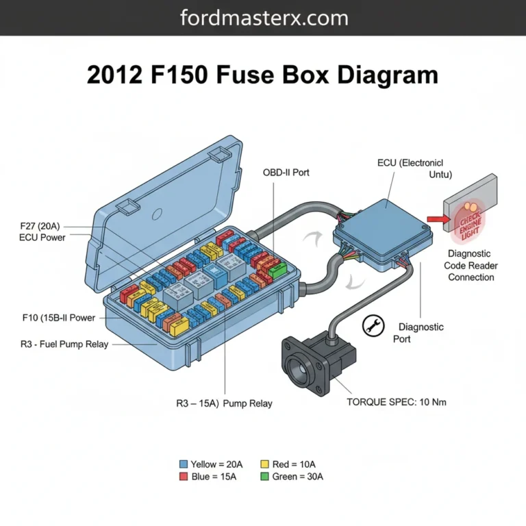
The 2010 Ford Escape features two primary fuse panels: the Battery Junction Box (BJB) located in the engine compartment near the air cleaner, and the Smart Junction Box (SJB) in the passenger footwell. Refer to the lid’s embossed legend to identify the 5A to 50A blade fuses protecting the ECU and OBD-II port.
📌 Key Takeaways
- The BJB handles high-current circuits (up to 60A), while the SJB manages interior lighting, door locks, and the OBD-II diagnostic port.
- Always match the replacement fuse amperage exactly; using a higher rating can cause permanent wiring harness damage or fires.
- Ensure the engine is off and the key is removed before handling fuses, maintaining a safe working environment.
- A common point of failure is corrosion in the BJB due to moisture, which often triggers intermittent electrical failures.
- If a circuit blows repeatedly, seek professional diagnostic assistance to trace short-to-ground conditions that exceed DIY repair scope.
Troubleshooting electrical gremlins in a 2010 Ford Escape requires a disciplined approach to circuit isolation and component testing. Whether you are dealing with a parasitic battery drain or a non-responsive fuel pump, the foundation of your diagnosis lies in the 2010 Ford Escape fuse box diagram. This vehicle platform utilizes two primary power distribution hubs: the Battery Junction Box (BJB) located in the engine bay and the Smart Junction Box (SJB) situated in the passenger cabin. Understanding the specific circuit protection, relay logic, and power flow path is essential for technicians tasked with restoring vehicle functionality. Failure to interpret these diagrams correctly often leads to unnecessary ECU replacement or misdiagnosis of ground faults when the underlying issue is merely a blown fuse or corroded bus bar.
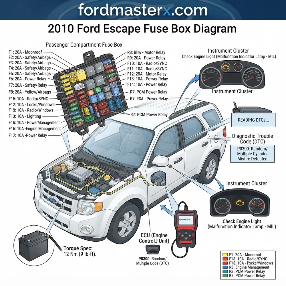
2010 Ford Escape Fuse Box Diagram: Component Identification
Recommended Best Deal Products


The 2010 Ford Escape utilizes a split electrical architecture. The Battery Junction Box (BJB) handles high-current circuits, while the Smart Junction Box (SJB) manages low-current interior systems and communication modules. Proper identification of blade fuses and micro-relays is critical for verifying power delivery to the ECU and peripheral systems.
The BJB is mounted on the driver side inner fender, protected by a plastic cover that displays the layout. The SJB, often referred to as the Central Junction Box, is located behind the passenger side kick panel. When reviewing the 2010 Ford Escape fuse box diagram, focus on the specific amperage ratings—using an incorrect rating can cause thermal damage to the harness or fire hazards.
| Circuit Function | Fuse/Relay ID | Amperage Rating |
|---|---|---|
| Fuel Pump Module | Fuse 41 (BJB) | 20A |
| Powertrain Control Module (ECU) | Fuse 34 (BJB) | 15A |
| ABS Control Module | Fuse 12 (BJB) | 40A |
| Ignition Switch Circuit | Relay 1 (SJB) | N/A |
| Cooling Fan Relay | Relay 6 (BJB) | N/A |
Note that the SJB is sensitive to moisture. If you notice signs of corrosion on the connector pins, it may cause intermittent CAN-bus errors or false diagnostic codes across the instrument cluster.
Common 2010 Ford Escape Fuse Box Diagram Issues and Symptoms
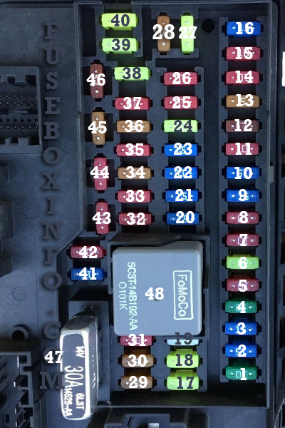
Faulty electrical distribution often manifests as cascading system failures. A short circuit in a non-essential accessory can draw enough current to compromise the ECU or interfere with OBD-II communication. When the check engine light illuminates, technicians must correlate the specific diagnostic code with the relevant fuse bank.
If your scanner reports a “No Communication” error with the ECU, the first step is to verify the 12V constant power feed (B+) and the switched ignition feed via the BJB. A blown fuse here prevents the ECU from initializing, effectively silencing the entire engine management system. Additionally, improper grounding is a leading cause of phantom electrical issues. Check the grounds near the battery tray and the main chassis-to-engine straps. If the engine experiences high oil pressure warnings or coolant flow fluctuations during electrical surges, investigate the common ground headers, as these can create feedback loops in the sensor data lines.
Never bridge a blown fuse with wire or metallic objects. This bypasses the safety mechanism, allowing excessive current to melt wire insulation and potentially cause a total vehicle loss due to fire.
Electrical symptoms are frequently linked to specific component failures. For instance, if the air conditioning compressor refuses to engage, verify the clutch relay in the BJB. Often, the relay contacts become pitted over time, increasing resistance and generating heat that eventually fails the relay coil.
Diagnostic Steps for 2010 Ford Escape Electrical Systems
Recommended Best Deal Products


A professional diagnostic approach relies on a digital multimeter (DMM) and the official 2010 Ford Escape fuse box diagram. Follow these procedures to isolate faults accurately:
1. Perform a Visual Inspection: Examine the fuse terminals for signs of heat stress, such as melted plastic or discoloration. Check for moisture intrusion in the SJB, especially around the bulkhead connectors.
2. Verify Supply Voltage: Use a DMM to test the voltage at both sides of the fuse while the circuit is under load. A significant voltage drop across the fuse indicates an oxidized contact or internal damage.
3. OBD-II Integration: If a diagnostic code persists after clearing it, hook up your scan tool and monitor live data. If a sensor (such as the oil pressure sensor) provides inconsistent readings, verify the power distribution to the sensor’s reference voltage (VREF) circuit.
4. Relay Testing: Use a dedicated relay tester or bridge the switched terminals (with the ignition off) to check for component actuation. If a relay clicks but the load does not activate, check for high resistance in the wiring harness between the relay and the end component.
5. Ground Integrity: Use the resistance (Ohms) setting on your multimeter to test the ground path of the fuse box. A reading higher than 0.5 Ohms indicates an insufficient ground connection.
When re-securing the fuse box housing or engine components after diagnostic work, always reference the OEM torque spec. Over-tightening fasteners on plastic enclosures leads to stress fractures and subsequent liquid contamination of the circuitry.
If you find that electrical faults coincide with engine mechanical issues—such as timing chain tensioner slack or timing misalignment—always confirm the electrical integrity of the Variable Valve Timing (VVT) solenoid circuit. These components are highly sensitive to voltage fluctuations and can trigger misleading diagnostic codes if the circuit protection is compromised.
2010 Ford Escape Fuse Box Diagram Questions Answered
How do I identify which relay controls the fuel pump in the 2010 Ford Escape?
Consult the underside of the BJB cover for the relay layout, which maps to the 2010 Ford Escape fuse box diagram. Usually, the fuel pump relay is located in the engine compartment BJB. You can verify it by listening for an audible click when the ignition is cycled to the “On” position without cranking the engine.
Can a faulty fuse cause my check engine light to stay on permanently?
Yes. If the ECU or a critical emission control sensor loses its power supply due to a blown fuse, the system will set a hard diagnostic code. Always clear the codes using an OBD-II scanner after replacing the faulty fuse to verify the repair.
Why does my scanner fail to connect to the OBD-II port?
Communication issues are often caused by a blown fuse associated with the cigarette lighter or auxiliary power outlet circuit, which often shares a bus with the OBD-II data link connector. Check the SJB for any blown 15A or 20A fuses labeled for accessory power.
Is it possible to upgrade fuse ratings to prevent future blowing?
Absolutely not. The fuse rating is engineered to protect the gauge of the wire used in that specific harness. Increasing the amperage rating creates a genuine risk of fire, as the wire will melt before the fuse blows during an overcurrent event. Always replace with the exact amperage indicated in the 2010 Ford Escape fuse box diagram.
How do I address a persistent “Battery Saver” relay error?
This usually indicates an issue within the SJB or a parasitic drain that is causing the battery management system to cut power to non-essential modules. Verify that the battery state of charge is sufficient and inspect the SJB for signs of electrical shorts or terminal oxidation.
Step-by-Step Guide to Understanding the 2010 Ford Escape Fuse Box Diagram
Recommended Best Deal Products


Identify – Consult the owner’s manual or lid cover to match the faulty component to the correct fuse number.
Locate – Gain access to the BJB in the engine bay or the SJB located behind the passenger side kick panel.
Reference – Use the fuse diagram to pinpoint the specific slot position for the suspected circuit.
Connect/Route – Use a multimeter probe to test for 12V power at the fuse test points if the component remains unresponsive.
Verify – Replace any blown fuse with one of the exact same amperage and observe if the check engine light or electrical failure persists.
Troubleshoot – If the issue remains, scan the vehicle for a diagnostic code using the OBD-II port to rule out deeper ECU communication errors.
If your Escape’s fuses check out fine, cross-reference our Ford wiring color code chart for circuit-level troubleshooting.