
1999 Ford F250 Fuse Box Diagram: 2026 Troubleshooting Guide

The 1999 Ford F250 features two main fuse panels: the interior cabin panel located to the left of the steering column and the Power Distribution Box under the hood. The interior panel handles cabin electronics like the instrument cluster and radio, while the engine bay box manages high-amperage circuits for the ECU and fuel pump.
📌 Key Takeaways
- The interior cabin panel utilizes mini-blade fuses ranging from 5A to 30A; always verify rating before replacement.
- The engine bay Power Distribution Box houses maxi-fuses up to 60A for primary system protection.
- Proper torque spec for battery terminal connections is 10-12 lb-ft to prevent voltage drops causing spurious codes.
- Corrosion on the firewall-side connector pins is the most frequent cause of intermittent power failure.
- Seek professional diagnostic assistance if the PCM exhibits signs of water intrusion or internal electrical shorts.
The 1999 Ford F250 represents a pivotal transition in the Super Duty lineage, marking the shift to a more robust electrical architecture required for the heavy-duty 7.3L Powerstroke and the Triton V8/V10 engines. When electrical anomalies arise, the 1999 Ford F250 fuse box diagram serves as the primary roadmap for diagnostic success. Whether you are chasing a parasitic drain affecting your ECU, investigating a phantom check engine light, or troubleshooting a non-responsive fuel pump relay, precise identification of circuit protection is essential. Misidentifying a circuit can lead to cascading electrical failures, potentially damaging the Powertrain Control Module (PCM). This technical guide provides the mapping, identification, and diagnostic procedures required for the 1999 model year’s unique electrical distribution systems.

Prime for Young Adults — 6 Months Free
Students and 18–24s get six months of Prime free, then half price.
Start 6 Months Free As an Amazon Associate I earn from qualifying purchases.
Locating the 1999 Ford F250 Fuse Box Diagram Panels
Recommended Best Deal Products


Understanding the physical geography of the 1999 Ford F250 electrical distribution system requires locating two distinct hubs: the Passenger Compartment Fuse Panel and the Power Distribution Box. The Passenger Compartment Fuse Panel, often referred to as the Central Junction Box (CJB), is located on the driver’s side, hidden behind the lower dash trim panel. To access this, you must depress the latch on the driver’s side kick panel cover. This area controls the cabin-side electronics, including the instrument cluster, radio, climate control, and secondary sensor circuits.
The Power Distribution Box, conversely, is located under the hood, situated on the driver’s side inner fender, near the firewall. This heavy-duty box houses the high-amperage fuses and relays responsible for engine management, including the ECU, fuel pump, and starter solenoid. Unlike the cabin panel, this enclosure is weather-sealed with a rubber gasket to prevent moisture ingress. When diagnosing engine-related issues—such as an intermittent check engine light or failure to start—this is your primary diagnostic site.
Navigating the Owner’s Manual and Field Identification
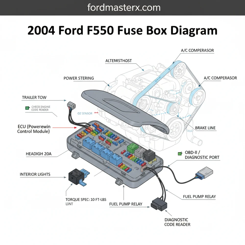
While the 1999 Ford F250 fuse box diagram is typically printed on the inside of the fuse cover, these decals often fade or become illegible over two decades of engine heat exposure. Always cross-reference the physical labels with the factory service manual. Be aware that the 1999 model year featured a “split” production cycle; some early-build 1999s may show variations compared to late-build models, particularly regarding towing relay configurations. Always confirm the specific part numbers on your existing fuses against the OEM requirement before conducting continuity tests.
If you are working on a 7.3L Powerstroke, prioritize the Power Distribution Box diagnostics. The Fuel Heater and Injector Driver Module (IDM) relays are frequent points of failure that can cause total engine shut-downs, often incorrectly attributed to fuel delivery issues.
1999 Ford F250 Fuse Box Diagram: Component Identification
Accurate identification of individual circuit loads prevents the improper use of high-amperage fuses in low-amperage sockets. The following table identifies critical circuits found within the under-hood Power Distribution Box and the interior Central Junction Box.
| Fuse # | Circuit Function | Amperage (A) |
|---|---|---|
| F101 | Powertrain Control Module (PCM) | 30A |
| F102 | Fuel Pump Relay | 20A |
| F103 | Instrument Cluster / OBD-II | 15A |
| F104 | Headlamp Low Beam (Left) | 15A |
| F105 | Headlamp Low Beam (Right) | 15A |
Relay and Circuit Breaker Mapping
Relays serve as electromagnetic switches that allow a low-current signal (from the ignition switch or ECU) to trigger a high-current path (for the cooling fan or fuel pump). If you hear a “clicking” sound without engine turnover, a faulty starter relay is the likely culprit. Conversely, if your cooling fans remain running after the engine is shut off, check for a welded relay contact. Always verify the relay pinout diagram against the replacement part to ensure compatibility, as Ford utilized specific ISO-standard relay footprints throughout the 1999 production run.
Common 1999 Ford F250 Fuse Box Diagram Symptoms
Recommended Best Deal Products


Electrical faults in the 1999 Ford F250 often manifest as a series of cascading symptoms. Because the ECU manages multiple engine parameters simultaneously, a single blown fuse or corroded relay can trigger a chain reaction.
Persistent Check Engine Light: If the ECU loses constant battery power, it may reset the KAM (Keep Alive Memory), causing the vehicle to revert to base fuel maps and immediately trigger a diagnostic code.
OBD-II Communication Loss: If your scan tool cannot establish a link, check the cigar lighter or auxiliary power point fuses, as these circuits often share ground paths with the OBD-II diagnostic port.
Short-to-Ground Errors: A blown fuse that immediately fails upon replacement indicates a dead short, often caused by chafed wiring in the engine harness, particularly near the oil pressure sensor or coolant temperature sensor leads.
Engine Hesitation: If the fuel pump relay in the Power Distribution Box is failing, you may experience erratic voltage drops, leading to unstable oil pressure readings and engine misfires under load.
Never substitute a higher-amperage fuse for a blown one. Doing so can cause thermal overload in the wiring harness, leading to melted insulation and potential vehicle fire. Always match the amperage rating specified by the manufacturer.

Audible — Listen Free for 30 Days
One free credit a month and thousands of titles included.
Listen Free for 30 Days As an Amazon Associate I earn from qualifying purchases.Diagnosis Steps for 1999 Ford F250 Electrical Faults
Logical troubleshooting follows a hierarchy of complexity: first, check the fuse; second, check the relay; third, check the harness for continuity.
1. Visual Inspection of the Fuse Block: Remove the cover and inspect the fuse elements. A thin, transparent window allows you to see the bridge. If the bridge is broken or the plastic housing is scorched, use an insulated fuse puller to extract it.
2. Voltage Testing: With the ignition in the “ON” position, use a digital multimeter (set to DC Volts) to measure the voltage on both test ports atop the fuse. If you see battery voltage (approx. 12.6V) on one side but 0V on the other, the fuse is open.
3. Relay Logic Testing: To test a relay, you can swap it with a known good one of the same part number (e.g., the horn relay). If the suspected component (like the AC compressor) begins working, the relay is the failed component.
4. Continuity and Resistance: If the fuse is intact but the circuit is dead, use an ohmmeter to check for continuity between the fuse socket and the load device. Excessive resistance (above 0.5 ohms) indicates high-resistance corrosion within the socket or wiring.
5. ECU Ground Verification: Inspect the ground strap locations near the firewall. If the ECU lacks a solid chassis ground, you may see erratic diagnostic codes related to timing chain sensors or coolant flow efficiency, even if the electrical system is otherwise sound.
When replacing relays, ensure your connections are clean of oxidation. If replacing the starter relay, verify that the mounting hardware is tightened to the correct torque spec of 8-10 lb-ft to ensure low-resistance contact with the chassis ground.
1999 Ford F250 Fuse Box Diagram Questions Answered
Recommended Best Deal Products


Why does my fuse blow immediately after replacement?
This indicates a short-to-ground somewhere in the downstream circuit. You must trace the wiring from the fuse block to the component (e.g., the fuel pump or blower motor) to locate chafed insulation touching the chassis.
How do I identify a bad ECU fuse?
The PCM/ECU power fuse is usually labeled within the Power Distribution Box. A failure here will result in a “no-start” condition and the scan tool will fail to connect via the OBD-II port.
Can a bad relay cause low oil pressure readings?
Indirectly, yes. If a relay fault affects the voltage supply to the instrument cluster or the ECU’s ability to process sensor data, the gauge readings may become erratic. Always verify actual oil pressure with a mechanical gauge to rule out physical engine wear.
Does the 1999 Ford F250 have a separate fuse for the timing chain sensor?
The Crankshaft Position Sensor (CKP) and Camshaft Position Sensor (CMP)—which monitor the timing chain synchronization—are typically powered via the main ignition-switched circuit. A fuse failure here will result in an immediate engine stall.
Where is the OBD-II diagnostic fuse located?
The OBD-II port is typically powered through the same circuit as the cigarette lighter or the auxiliary power outlet. If your scanner won’t power on, check the interior fuse panel for a blown 20A accessory fuse.
By mastering the layout provided in the 1999 Ford F250 fuse box diagram, you can transition from trial-and-error part swapping to precise, analytical repairs. Always keep a spare set of fuses in the glove box, as these electrical components are the first line of defense against catastrophic failures in your Ford Super Duty’s complex electrical grid. If you continue to face electrical instability, remember to check your battery ground cables and alternator output, as low system voltage can manifest as phantom fuse failures across all vehicle systems.
Step-by-Step Guide to Understanding the 1999 Ford F250 Fuse Box Diagram
Identify – Locate the specific fuse panel associated with your malfunctioning component using the diagrams.
Audible Premium Plus — Annual Membership
12 audiobook credits up front, plus the full Audible catalogue.
See Annual Plans As an Amazon Associate I earn from qualifying purchases.Locate – Gain access by removing the interior kick panel or the under-hood distribution box cover.
Reference – Match the suspect component’s number to the diagram legend to pinpoint the specific fuse or relay.
Connect/Route – Use a multimeter to verify 12V power at the fuse test ports, ensuring stable voltage output.
Verify – Replace any failed fuse and scan for stored diagnostic codes to ensure the system is operational.
Troubleshoot – Inspect the harness pins for corrosion or heat damage if the new fuse blows immediately upon installation.
One Comment