Ford Taurus 2026 Drum Brake Diagram: Component Breakdown

The Ford Taurus drum brake assembly utilizes a self-adjusting star wheel, primary and secondary shoes, and a return spring configuration. Critical adjustment occurs at the star wheel assembly. Ensure the wheel cylinder seals are intact and the hold-down pins are properly seated to prevent uneven brake wear.
📌 Key Takeaways
- Primary brake shoe lining must face toward the front of the vehicle for correct geometric operation.
- The self-adjuster cable must be routed through the guide at the top of the assembly to maintain proper clearance.
- Always adhere to the manufacturer-specified wheel lug torque spec of 100 lb-ft to prevent rotor or drum warping.
- Brake fluid leaks at the wheel cylinder are the leading cause of spongy pedals and reduced stopping performance.
- If a check engine light or OBD-II code related to ABS appears after service, verify the sensor air gap and wiring integrity.
Maintaining the rear braking system on older Ford Taurus models requires a precise understanding of the mechanical linkage and hydraulic components housed within the drum assembly. Unlike modern disc brake setups monitored by advanced ECU modules, the drum brake system relies on a purely mechanical self-adjuster mechanism and hydraulic pressure from the wheel cylinder to initiate friction. For the professional technician or the serious automotive enthusiast, referencing an accurate Ford Taurus drum brake diagram is essential for ensuring correct spring orientation, shoe placement, and cable tension. Improper assembly here can lead to premature wear or, more critically, loss of secondary braking capacity, which remains a key safety performance metric regardless of the lack of an electronic diagnostic code for these mechanical parts.
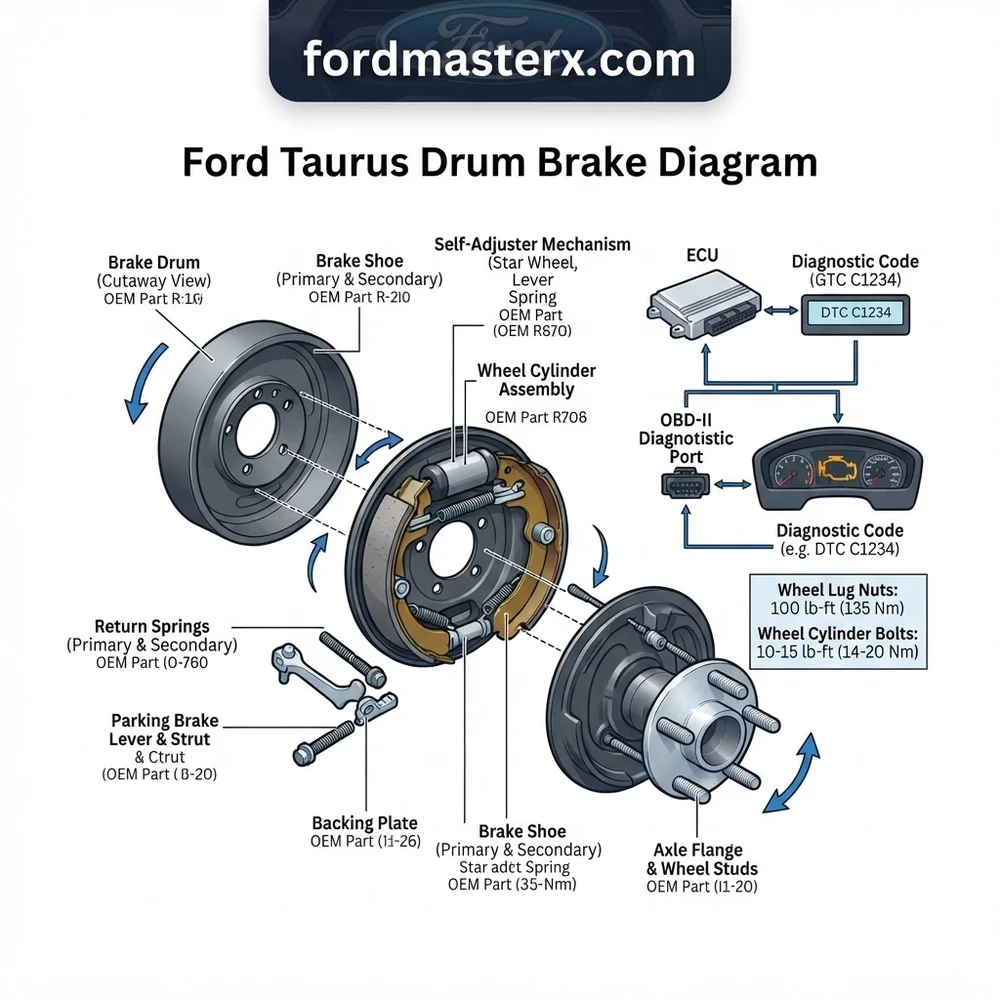
Ford Taurus Drum Brake Diagram: Every Component Labeled


To successfully service the rear drum system on vehicles spanning the early-to-mid generations, you must be able to identify every spring and pivot point shown in the Ford Taurus drum brake diagram. The assembly is a complex interplay of hydraulic force and mechanical leverage, where the wheel cylinder translates fluid pressure into shoe expansion against the inner diameter of the drum. Understanding the hierarchy of these parts is vital for both rebuilds and routine maintenance.


| Component | Function | Technical Note |
|---|---|---|
| Wheel Cylinder | Hydraulic actuator | Must be free of leaks; check bore for pitting. |
| Star Wheel Adjuster | Maintains shoe-to-drum clearance | Clean and lubricate threads with high-temp grease. |
| Primary Shoe | Leading shoe (shorter lining) | Often faces the front of the vehicle. |
| Secondary Shoe | Trailing shoe (longer lining) | Houses the parking brake lever attachment. |
| Return Springs | Retract shoes post-braking | Replace if stretched or showing signs of heat fatigue. |
The primary shoe is distinguishable by its shorter lining material, which is engineered to accommodate the geometry of the leading edge in the rotation of the brake drum. Conversely, the secondary shoe possesses a longer lining, designed to handle the majority of the stopping torque. If your Ford Taurus drum brake diagram shows mismatched shoe placement, it will result in “grabby” brakes or premature fading. Always inspect the parking brake cable attachment points for rust, as seized cables are a common point of failure that often masquerades as a seized wheel cylinder or a faulty self-adjuster mechanism.
Technical Specifications for Ford Taurus Drum Brake Service


Precision is mandatory when dealing with drum brake tolerances. While technicians frequently scan for a check engine light or pull an OBD-II diagnostic code to solve engine performance issues—such as those related to a worn timing chain or erratic oil pressure—the drum brake system remains a purely mechanical domain that requires manual measurement. Operating outside of these OEM specifications can compromise the entire braking circuit.
| Spec Category | Parameter/Limit | Recommended Tool |
|---|---|---|
| Drum Max Diameter | Stamped on drum (e.g., 228.6mm) | Drum Micrometer |
| Shoe Lining Min Thickness | 1.5mm – 2.0mm | Vernier Caliper |
| Wheel Cylinder Torque | 12-15 ft-lbs (Fastener) | Calibrated Torque Wrench |
| Brake Fluid Type | DOT 3 or DOT 4 | Pressure Bleeder |
When servicing, remember that brake dust can contain asbestos in older vehicles. Always utilize proper safety equipment and avoid using compressed air to clean the assembly. Instead, use a certified solvent-based brake cleaner to prevent the accumulation of debris that can interfere with the star wheel adjuster.
Common Ford Taurus Drum Brake Diagram Issues and Symptoms

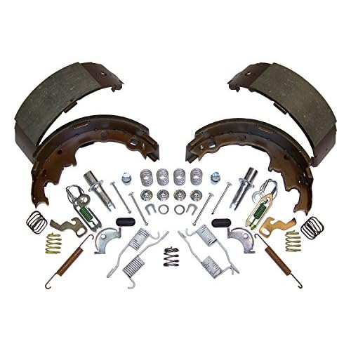

Failure in the drum brake system typically presents through distinct sensory feedback. Unlike coolant flow issues, which may trigger a high-temperature warning, or fluctuating oil pressure that requires immediate sensor verification, drum brake degradation is often audible or tactile. Referencing your Ford Taurus drum brake diagram during inspection helps isolate the specific source of these common failure points:
- Squealing or Grinding: This usually indicates that the brake shoe lining has worn down to the steel backing plate. If you hear this, immediate drum inspection is required to check for scoring that might exceed the machining limit.
- Seized Star Wheel Adjuster: If the vehicle loses its “firm” pedal feel over time, the self-adjuster is likely frozen due to rust or grit. The shoes fail to move closer to the drum as the lining wears, causing excessive pedal travel.
- Wheel Cylinder Leakage: A “soft” or “spongy” pedal is the classic symptom of a leaking wheel cylinder. Check the bottom of the backing plate for fluid trails, which would contaminate the brake shoes and necessitate a full replacement of both the cylinders and shoes.
- Dragging Brakes: If the vehicle feels sluggish or you smell burning brake material, the return springs may have lost tension, or the parking brake cable is stuck in the applied position.
- Excessive Brake Dust: While some dust is normal, a heavy, thick layer can interfere with the movement of the hold-down pins, causing the shoes to bind and unevenly wear.
Steps to Diagnose and Service Ford Taurus Drum Brakes
To perform an effective service, follow a logical diagnostic flow that begins with a physical inspection before moving to component removal. Just as you would verify ECU communication before diagnosing an intermittent sensor, verify the state of your mechanical brake hardware before attempting an adjustment.
Ensure the vehicle is secured on jack stands on a level surface. Never rely solely on a hydraulic floor jack while working inside the wheel well.
- Initial Assessment and Drum Removal: Remove the wheel and the brake drum. If the drum is seized, use a rubber mallet to tap the perimeter to break loose the rust bond. Once removed, inspect the inner surface for scoring. If the drum diameter exceeds the OEM specification found in your manual, discard the unit.
- Cleaning and Inspection: Using brake cleaner, remove all accumulated dust. Inspect the wheel cylinder boots for signs of fluid weeping. If fluid is present, the seals have failed; rebuild or replace the cylinder immediately.
- Hardware Removal: Use a brake spring tool to remove the return springs. Be careful of tension; these springs are under high load. Remove the hold-down pins and springs next. As you disconnect the springs, reference the Ford Taurus drum brake diagram to ensure you note the specific orientation of the hardware, as the leading and trailing shoes are not always interchangeable.
- Parking Brake Cable Disconnect: Remove the parking brake lever from the secondary shoe. Inspect the cable for fraying or restriction. A seized cable is the most common cause of premature secondary shoe wear.
- Star Wheel Adjuster Service: Disassemble the adjuster assembly. Clean the threads with a wire brush and apply a light coat of high-temperature brake grease. Verify that the star wheel turns freely and that the ratchet spring correctly engages the teeth.
- Reassembly and Clearance Setting: Install the new shoes, ensuring the primary shoe (shorter lining) faces forward. Reattach the parking brake cable and the spring hardware in the reverse order of removal. Use the star wheel to adjust the shoes until a light drag is felt when rotating the drum by hand.
- System Bleeding: Since the wheel cylinder was disturbed, bleed the brake lines to ensure no air bubbles are trapped in the system. Use a vacuum bleeder to pull fresh fluid through until the flow is clear and free of bubbles.
- Final Verification: Before road testing, ensure the parking brake lever is correctly adjusted. A loose lever indicates that the self-adjuster is not correctly set, which can lead to a low brake pedal during subsequent operation.
Ford Taurus Drum Brake Diagram Questions Answered
Does the Ford Taurus drum brake diagram change based on the production year?
Yes, while the core operating principle remains consistent, hardware configurations such as the specific spring attachment points and the design of the automatic adjuster can vary between early SHO models and later base-trim variants. Always check the specific service manual for your exact vehicle year and engine designation.


Can a fault in the drum brakes cause a check engine light or store a diagnostic code?


Generally, no. The drum brake system is mechanical and does not communicate with the engine control unit (ECU). However, if your vehicle is equipped with an Anti-lock Braking System (ABS), a malfunctioning wheel speed sensor near the drum assembly could trigger an ABS warning light and store an OBD-II diagnostic code related to brake system performance.
What is the correct torque spec for the drum retaining screws?



Consult your specific technical manual, but typically, these screws are designed primarily for positioning and do not require high torque; usually, 5-10 ft-lbs is sufficient. The wheel lug nuts are the primary fasteners that hold the drum securely against the hub at higher torque specs.
How often should I service the self-adjuster shown in the diagram?


The self-adjuster should be cleaned and lubricated during every major brake service or whenever the drums are removed. If the vehicle is used in areas with heavy road salt usage, checking the adjuster mechanism every 20,000 miles is recommended to prevent seizure.

Is it necessary to replace the wheel cylinders when replacing shoes?


It is not strictly necessary unless they show signs of leakage or internal bore pitting. However, given the labor involved in accessing the assembly, many technicians perform a proactive replacement of wheel cylinders to ensure system reliability for the next 50,000 miles.
Step-by-Step Guide to Understanding the Ford Taurus Drum Brake Diagram
Identify – Inspect the diagram to match the specific left or right side shoe orientation.
Locate – Position the wheel cylinder at the 12 o’clock position on the backing plate.
Reference – Use the diagram to verify the color-coding and placement of the primary versus secondary return springs.
Connect/Route – Install the self-adjuster cable through the top guide and connect the adjuster lever to the star wheel.
Verify – Torque all mounting hardware to OEM specifications and check for fluid leaks at the cylinder lines.
Troubleshoot – Test for dragging or binding; scan for an OBD-II diagnostic code if the ABS light remains active.