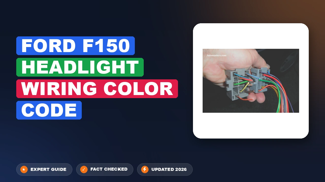
ford f150 headlight wiring color code Decoded for Repairs

Upgrading or repairing the headlights on your Ford F-150 should be a straightforward mechanical task, but the modern electrical architecture of these trucks is significantly more complex than older models. Relying on generic, internet-sourced “color code” charts or anecdotal forum advice frequently leads to Body Control Module (BCM) damage, blown fuses, or persistent, costly electrical shorts. This guide provides the professional methodology required to identify your specific wiring harness, utilize the correct diagnostic tools, and complete your lighting project without compromising your truck’s sensitive electronic systems.
Understanding the Evolution of Ford F150 Headlight Wiring
Recommended Best Deal Products


The electrical architecture of the F-150 has undergone a radical transformation over the last decade. Understanding these changes is critical for anyone performing maintenance or custom lighting installs.
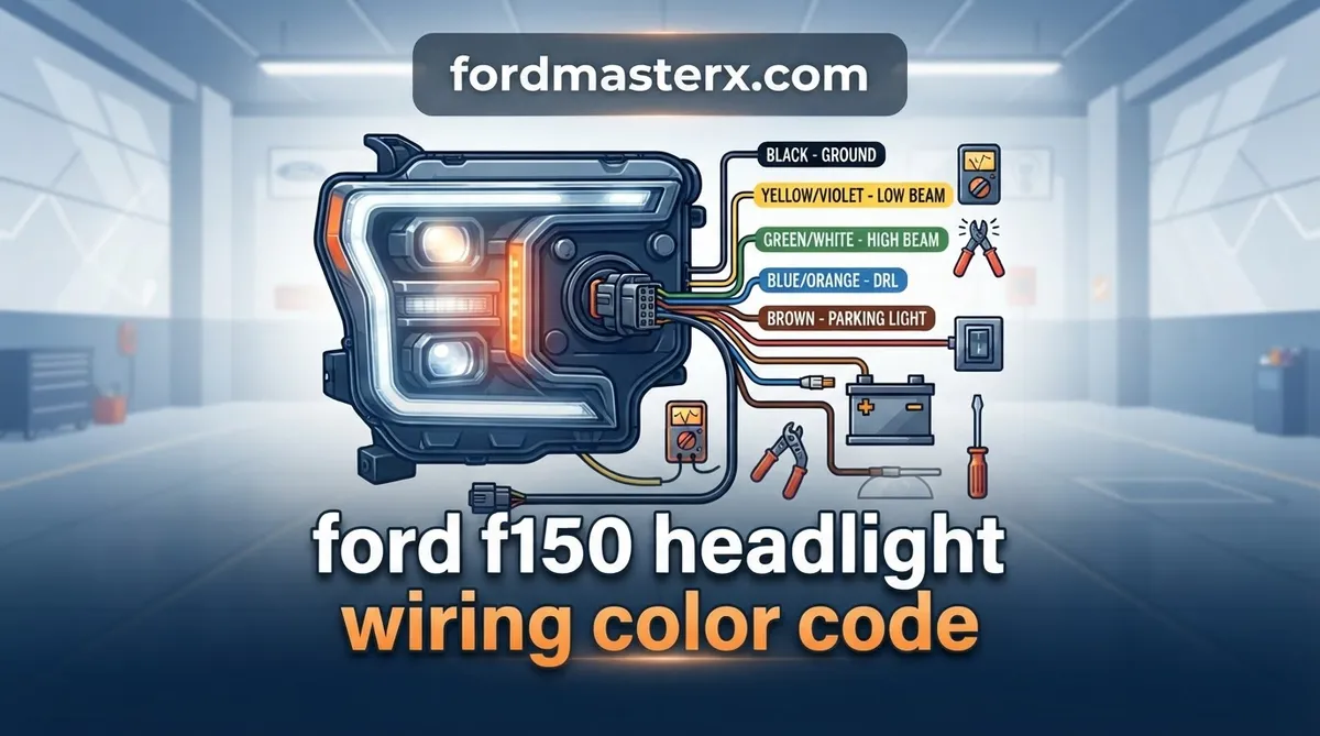
📤 Share Image

Why Wire Colors Change Across Model Years
Wiring harnesses for the Ford F-150 are not standardized across the entire production run. A 2015 XLT may use entirely different color-coded leads for the same headlight functions as a 2024 Platinum. Ford frequently updates harness schematics during mid-cycle refreshes to accommodate new lighting options, such as LED signature lighting or adaptive high beams. Professional technicians know that referencing a wiring diagram for the wrong production month is a common cause of electrical failure.

The Role of the Body Control Module (BCM)
Modern F-150s no longer use standard relay-based switching for headlights. Instead, the BCM manages lighting via the Can-Bus network. This system monitors current draw with extreme precision. If you introduce an aftermarket component that draws too much power, or if you create a minor short, the BCM will immediately shut down that circuit to prevent fire damage. This is why aftermarket “lamp out” warnings are so prevalent when inferior LEDs are installed without appropriate load resistors or driver modules.
Halogen vs. LED Circuit Logic
The logic powering halogen bulbs is significantly simpler than the Pulse Width Modulation (PWM) signals used for factory LED systems. PWM pulses voltage at high frequencies to manage light intensity and thermal load. Attempting to tap into a PWM circuit for an accessory power source will lead to flickering or total system failure. The complexity of these circuits dictates that visual inspection of wire colors is essentially useless—data verification is the only path to success.
Professional Methods to Identify Ford F150 Headlight Wiring Circuits
📋
Diagnostic Verification Steps
Recommended Best Deal Products


Always disconnect the negative battery terminal before probing or modifying wires. This prevents accidental shorts during the identification process.
Use a high-quality digital multimeter. Set it to DC voltage to test for 12V signals when the switch is engaged, and use the continuity (ohm) setting to identify the ground wire.
Insert a thin needle-probe adapter into the rear of the connector cavity. Never pierce the insulation of the wire itself, as this introduces moisture and eventual corrosion.
Essential Tools for Circuit Verification
The industry-standard tool for this job is a digital multimeter. Avoid test lights; on BCM-controlled systems, test lights can draw enough current to be interpreted as a short or a fault by the module, potentially frying sensitive solid-state drivers. A reliable digital multimeter with alligator clips and back-probing needles is the only trusted way to identify high, low, and ground circuits accurately.
Avoiding Destructive Tapping Methods
Never use “scotch locks” or cheap plastic wire taps. These devices physically compromise the wire, allowing moisture to enter the copper strands, leading to high-resistance corrosion. Given the sensitivity of the F-150’s electrical system, a corroded connection will almost certainly lead to intermittent headlight flickering or total system failure down the road.
Standard Ford F150 Headlight Wiring Pinout References
While specific wire colors change, the physical layout of the connector is often consistent within specific generations. The table below represents a common late-model 8-pin connector configuration, but remember: your specific VIN is the final word.
Locating Your Specific VIN Wiring Schematic
The only reliable, professional source for exact wiring information is the Ford factory service manual or the Motorcraft Service Information portal. By inputting your VIN, you access the exact schematic intended for your specific truck’s build date and trim level. Do not trust third-party diagrams found in open-source forums, as they often conflate different year ranges.
Troubleshooting Ford F150 Headlight Wiring Circuit Failures
Recommended Best Deal Products

If your headlights have ceased functioning, the BCM may have “latched” a fault code. Changing a bulb or wiring will not restore power until the BCM detects the short has been cleared and resets its internal logic, sometimes requiring a diagnostic scanner to clear the DTC.
Testing for BCM Load Protection Triggers
- Load Testing: If a fuse tests okay, use a load tester to verify the circuit can actually sustain current. A standard multimeter measures voltage, not amperage under load, which is why a circuit can show 12V but fail to power a light.
- Ground Point Inspection: Inspect the chassis ground points near the radiator support. These points are notorious for accumulating dirt and oxidation, leading to flickering, dim lighting, or total signal loss.
- Overcurrent Awareness: High-draw aftermarket light bars or LEDs frequently cause the BCM to cut power. Always use a dedicated relay harness triggered by the original signal to isolate aftermarket draws from the truck’s BCM.
Industry Data
Electrical faults linked to aftermarket modifications.
Accuracy rate of VIN-specific diagrams vs. forum data.
Expert Recommendations for Reliability
Diagnostic Precision
Always rely on a digital multimeter to confirm your circuit paths rather than relying on wire color identification.
Proper Load Management
Use dedicated relay harnesses for all high-draw aftermarket lighting to protect your sensitive BCM electronics.
When soldering any repairs, use marine-grade heat-shrink tubing with internal adhesive. This prevents moisture ingress, which is the primary killer of automotive electrical connections in the F-150 chassis.
Navigating the Ford F150 headlight wiring color code requires patience and technical precision. By prioritizing diagnostic verification over speculative data, you ensure the longevity of your truck’s electrical system. Modern BCM-controlled architectures are highly intolerant of amateur mistakes, so treat every wiring project as an opportunity to implement clean, factory-grade repairs. Before you cut into your harness, verify your circuit with a multimeter—your truck’s electronics will thank you.
Ford f150 Headlight Wiring Color Code: Frequently Asked Questions
How do I identify which wire is high beam?
To identify the high beam wire, use a digital multimeter. Set the truck to the ‘High Beam’ position with the engine off but the key in the accessory position. Probe the back of the harness at the headlight connector. The wire that registers 12V relative to the chassis ground is your high beam lead. Always verify against the low beam signal to ensure you have isolated the correct circuit.
Why don’t the wire colors match the manual?
Ford frequently changes wire colors mid-model year based on the supplier for the wiring harness assembly. Additionally, different trim levels (XL vs. Platinum) utilize different harnesses to accommodate varying features like HID, LED, or Halogen systems. Never rely exclusively on color; always verify the function of each pin using a multimeter to confirm signal flow before making permanent modifications to the harness.
Can I use a test light on modern Ford lighting circuits?
No, using a traditional incandescent test light is highly discouraged. Modern F-150s use sensitive BCMs and CAN-bus communication. A test light can draw too much current, potentially damaging the BCM’s internal drivers or triggering fault codes. Always use a high-impedance digital multimeter (DMM) or a logic-safe LED test light specifically designed for automotive computer-controlled systems to ensure the safety of your vehicle’s electronics.
Where is the ground point for the headlight harness?
The primary ground points for the headlight assemblies are typically located on the inner front fender aprons, directly behind the headlight housings. You will see several black wires bolted to the chassis via a ring terminal. Over time, these points collect dirt, moisture, and oxidation. If you experience dim lighting or intermittent failures, cleaning these ground terminals with a wire brush is the most professional first step.
What is the consequence of miswiring a headlight circuit?
Miswiring can lead to immediate failure of the Body Control Module (BCM), which is expensive to replace. At a minimum, you will likely blow a fuse or trip a soft-code in the truck’s computer. In severe cases, back-feeding voltage into the BCM can cause permanent board-level damage, leading to complex, recurring electrical issues that are difficult to diagnose and costly to resolve at a dealership.