2008 Ford F250 Fuse Box Diagram: 2026 Troubleshooting Guide

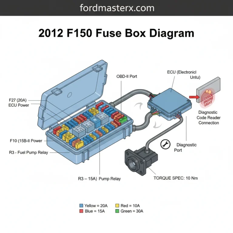
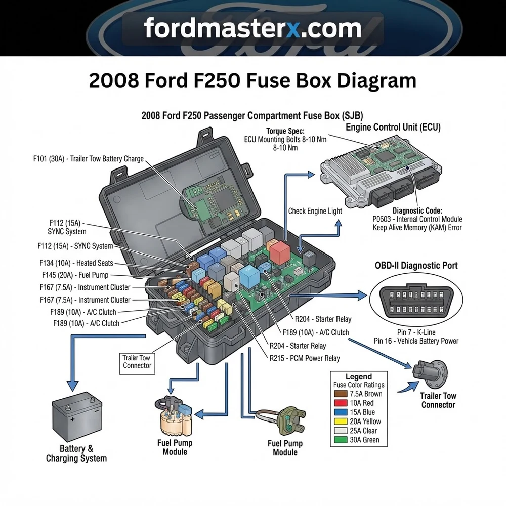
The 2008 Ford F250 features a Power Distribution Box in the engine compartment and a Central Junction Box inside the cabin under the passenger side dash. Refer to the interior lid labels for amperage ratings. Always verify power flow using a multimeter before replacing relays or fuses linked to the ECU.
📌 Key Takeaways
- The Power Distribution Box contains high-amperage J-case fuses ranging from 20A to 60A.
- Internal Smart Junction Box (SJB) corrosion is a frequent cause of intermittent lighting or power window failure.
- Always torque battery terminal connections to 8-10 lb-ft to prevent erratic voltage drops.
- A blown fuse in the fuel pump circuit is the most common cause of no-start conditions in these models.
- If diagnostic codes persist after fuse replacement, seek professional ECU analysis to avoid damaging electronic modules.
Maintaining the complex electrical architecture of a Super Duty truck requires a precise understanding of power distribution. The 2008 Ford F250 utilizes an intricate electrical system where reliable performance hinges on the integrity of its primary and secondary junction boxes. Whether you are troubleshooting a persistent check engine light, diagnosing an ECU communication failure, or tracing a parasitic draw that compromises your 12V battery, access to an accurate 2008 Ford F250 fuse box diagram is essential. This guide provides technical specifications and diagnostic procedures to help fleet managers and master technicians isolate circuit failures efficiently, ensuring your vehicle remains operational under demanding load conditions.
Navigating the 2008 Ford F250 Fuse Box Diagram Locations
Recommended Best Deal Products


The 2008 Ford F-250 Super Duty utilizes two primary electrical distribution centers, each serving distinct subsystems within the vehicle architecture. Misidentifying these locations is a common error that leads to wasted diagnostic time. The Power Distribution Box (PDB) is located in the engine compartment on the passenger side, positioned against the firewall. This unit houses the high-amperage fuses and relays required for engine management, cooling fan operation, and primary ignition circuits. It is the first point of inspection when dealing with no-start conditions or issues related to the engine’s coolant flow and oil pressure sensor inputs.
The second unit, known as the Smart Junction Box (SJB), is located inside the cab, mounted on the passenger side kick panel. The SJB acts as the gateway for body electronics, including the instrument cluster, interior lighting, power windows, and communication with the OBD-II diagnostic port. Unlike the PDB, which handles raw power distribution, the SJB is a sophisticated control module that interfaces directly with the ECU to manage vehicle security and accessory power.
Consulting the official Ford F-250 Owner’s Manual in tandem with your schematic is critical for 2008 models, as trim levels—ranging from XL to King Ranch—may include auxiliary circuits for trailer brake controllers or snowplow prep packages that alter standard fuse arrangements. When referencing the 2008 Ford F250 fuse box diagram, ensure you are identifying the correct board revision, as mid-year production changes sometimes introduced updated relays for the fuel pump and ignition modules. Always disconnect the negative battery terminal before probing terminals in the SJB to prevent accidental short-circuiting of the CAN-bus lines.
When testing for voltage drop across these fuse boxes, always use a high-impedance digital multimeter. Loading the circuit with a standard test light can damage sensitive ECU logic gates if back-fed through a ground-side switched circuit.
Component Identification in Your 2008 Ford F250 Fuse Box Diagram

To interpret a 2008 Ford F250 fuse box diagram effectively, you must understand the interplay between the fuses, relays, and diodes within the circuit paths. The PDB and SJB are not merely containers; they are active components of the vehicle’s electrical matrix. The following table identifies standard hardware found within these distribution centers and their specific roles in protecting your vehicle’s sub-systems.
| Component Type | Primary Function | Diagnostic Indicator |
|---|---|---|
| Mini/Maxi Fuses | Overcurrent protection for discrete circuits | Visible filament gap or high resistance |
| ISO Relays | High-current switching for ECU and fuel pump | Audible click missing during ignition |
| Circuit Breakers | Thermal protection for power window motors | Self-resetting cycle during operation |
| Fuse Puller Tool | Non-conductive removal of glass/blade fuses | Prevents terminal fatigue/bending |
Using the correct fuse puller is mandatory to prevent terminal deformation inside the SJB. Many technicians overlook the condition of the fuse sockets themselves; excessive heat buildup, often resulting from a loose crimp or high-resistance connection, can lead to melting of the plastic housing. If you find a burnt terminal, do not simply replace the fuse. You must inspect the wiring harness on the underside of the box for heat-damaged insulation, which could indicate a short circuit elsewhere in the loom.
When reviewing the diagram, pay close attention to relays labeled for the PCM (Powertrain Control Module). Failure of these relays is a common point of failure that mimics a dead ECU. Because the 2008 model uses heavy-duty architecture, the torque spec for the large power input nuts on the PDB is 8-10 Nm. Exceeding this torque can crack the plastic housing or compromise the copper bus bars underneath, leading to intermittent power delivery to the engine management system.
Common Symptoms of 2008 Ford F250 Fuse Box Diagram Failures
Recommended Best Deal Products



A failure within the electrical distribution system often presents as a constellation of symptoms rather than a single event. When the ECU loses its stable 12V supply, the most immediate indication is a check engine light accompanied by a P0606 or P0607 diagnostic code. These codes signal a potential processor fault, but in many instances, they are actually symptoms of low voltage or “dirty” power reaching the module from a corroded terminal within the Power Distribution Box.
Another frequent symptom involves the interaction between the SJB and the vehicle’s OBD-II port. If your diagnostic scanner fails to communicate with the vehicle despite the ignition being in the ‘ON’ position, the culprit is often a blown fuse for the diagnostic data link connector (DLC) or a communication error within the SJB’s internal board. If you notice the check engine light flashing erratically during acceleration, it may indicate a voltage spike or drop caused by a vibrating, loose relay in the PDB, which effectively interrupts the electrical signals managing the timing chain position sensors or oil pressure monitoring.
Never attempt to bypass a fuse with a higher amperage rating or a jumper wire. Doing so removes the fire protection for the circuit and can lead to immediate wiring harness melting or ECU destruction.
Environmental factors, such as water ingress, also plague these specific fuse boxes. Because the PDB is located in the engine bay, moisture can compromise the seals, leading to green oxidation on the metal contacts. This oxidation increases resistance, causing voltage drops that prevent the ECU from maintaining consistent oil pressure readings. If you suspect an electrical failure, the first step is to remove each relay and inspect for signs of corrosion or “telltale” burn marks on the spade terminals.
Diagnosis Steps for Electrical Faults in the 2008 Ford F250
1. Verify Battery Health: Before condemning the electrical center, ensure your 12V battery is load-tested and terminals are clean. An underrated battery or loose ground strap often triggers false electrical fault codes in the ECU.
2. Isolate the Fault: If you suspect a specific circuit is failing, locate it on your 2008 Ford F250 fuse box diagram. Check the fuse continuity using a multimeter set to ohms; a reading of “OL” indicates an open circuit.
3. Check Relay Functionality: If the fuse is intact but the device remains inactive, perform a “click test.” Use a fused jumper wire to bypass the relay contacts to see if the component engages. If it does, the relay coil or the command signal from the PCM is at fault.
4. Inspect the Wiring Harness: Trace the wire from the fuse box to the component. Look for signs of chafing, especially where the harness passes near the engine block or transmission bell housing. High heat can weaken the insulation, leading to intermittent shorts.
5. Analyze Terminal Tension: With the battery disconnected, use a small pick tool to test the resistance of the female terminals inside the fuse box. If a terminal is loose, it cannot maintain proper contact with the fuse or relay blade, leading to arcing and heat accumulation.
6. Scan and Clear Diagnostic Codes: After identifying and repairing the fault, use an OBD-II scanner to clear all stored codes. Monitor the system for a drive cycle to ensure the ECU has regained stable communication across all sensor loops.
Diagnostic Voltage Check: With the engine idling, the voltage at the PDB main input should be within 0.2V of the alternator output. A discrepancy greater than 0.5V suggests high resistance in the primary cabling.
2008 Ford F250 Fuse Box Diagram Questions Answered
Recommended Best Deal Products


How do I know if the Smart Junction Box is damaged?
The SJB is considered damaged if you observe interior lighting flickering, power locks operating sporadically, or if multiple non-related circuits (e.g., fuel pump and wipers) fail simultaneously. These units are programmed to the vehicle’s VIN and often require dealer-level diagnostic tools for reflashing if replacement is necessary.
Can I upgrade the wiring if my fuse box keeps melting?
No. Melting is a symptom of excessive resistance, usually caused by oxidation or a loose terminal. Upgrading the wire gauge will not fix the underlying contact issue. You must replace the affected terminal or the entire distribution block to restore the factory-intended current flow.
Why does my diagnostic scanner report a communication error?
This usually stems from a blown fuse in the SJB that powers the OBD-II diagnostic port. Check your 2008 Ford F250 fuse box diagram for the “DLC” (Data Link Connector) fuse. If that is intact, verify that the ECU has power and ground, as the port cannot communicate if the ECU is offline.
Is it safe to clean the fuse box terminals with contact cleaner?
Yes, using an electronics-grade, non-residue contact cleaner is recommended for minor oxidation. Ensure the battery is disconnected and the board is completely dry before restoring power. Do not use abrasive brushes, as they can remove the conductive plating from the terminals, which will only accelerate future corrosion.
How do I handle ECU faults related to the 2008 Ford F250 fuse box?
If your ECU is throwing power-related codes, verify the voltage at the ECU power pins using the wiring schematic. A failing relay in the PDB is a common, inexpensive fix compared to replacing the ECU itself. Always exhaust your search for loose connections or corroded relays before considering a module replacement.
Step-by-Step Guide to Understanding the 2008 Ford F250 Fuse Box Diagram
Identify – Locate the fuse box cover and verify the specific circuit number for the failing component.
Locate – Gain access to the engine bay box near the driver side or the interior SJB located beneath the passenger footwell panel.
Reference – Use the diagram to cross-match the physical fuse position with the color-coded amperage rating.
Connect/Route – Test for voltage at the test points on top of the fuse using a multimeter to confirm if power is reaching the load side.
Verify – Replace the faulty fuse or relay, then clear any existing diagnostic code from the ECU using an OBD-II scan tool.
Troubleshoot – If the fuse blows again immediately, inspect the wiring harness for signs of wear, abrasion, or shorts to ground.