
2002 Ford F350 Fuse Box Diagram: 2026 Troubleshooting Guide

The 2002 Ford F350 features a primary fuse panel located in the cabin to the left of the steering column and a Power Distribution Box in the engine bay. These panels manage power to the ECU, fuel pump, and OBD-II port. Verify continuity using a multimeter if fuses show signs of terminal corrosion.
📌 Key Takeaways
- The interior panel handles 12V ignition switched power, while the engine bay box houses high-amperage maxi-fuses (30A-60A) for major systems.
- Always cross-reference the owner’s manual diagram with the physical fuse block as towing packages may alter specific pinout configurations.
- When tightening terminal connectors during repair, apply a torque spec of 8-10 lb-in to prevent stripped threads or excessive resistance.
- A common failure point is the ‘blown’ fuse caused by shorted OBD-II wiring or moisture intrusion causing corrosion at the fuse spade contacts.
- If a fuse blows repeatedly after replacement, perform a parasitic draw test before seeking professional electrical diagnostic help.
When maintaining the electrical architecture of a Super Duty truck, the 2002 Ford F350 fuse box diagram serves as the primary technical blueprint for resolving power distribution faults. Whether you are addressing a no-start condition in a 7.3L Powerstroke or troubleshooting intermittent sensor feedback, identifying the correct relay and fuse locations is essential. This guide provides the high-level mapping required to navigate both the Central Junction Box (CJB) located inside the cabin and the Battery Junction Box (BJB) situated in the engine bay. Utilizing these schematics correctly ensures that you maintain system integrity while avoiding damage to sensitive electronic control units or wiring harnesses.
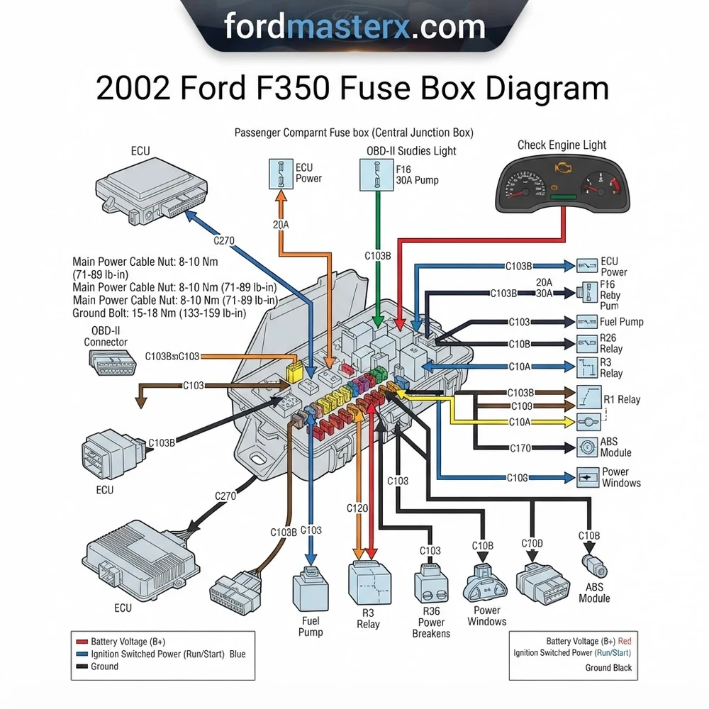
Component Identification for 2002 Ford F350 Fuse Box Diagrams


The electrical system of the 2002 Ford F350 utilizes two distinct distribution centers to manage the high current demands of a heavy-duty chassis. The Battery Junction Box (BJB) is located in the engine compartment, typically mounted on the driver’s side fender apron. This unit manages high-amperage feeds, including the starter relay, alternator output, and primary power for the ECU. Understanding the BJB configuration is critical when diagnosing major failures, such as a complete loss of power to the powertrain control module or primary lighting circuits.


Conversely, the Central Junction Box (CJB), often referred to as the interior fuse panel, is located beneath the driver’s side dashboard. This panel manages low-current interior components, including the instrument cluster, radio, power windows, and the OBD-II diagnostic link connector. Accessing this panel requires removing the lower trim cover. When reviewing the 2002 Ford F350 fuse box diagram for the interior panel, note that several circuits are protected by circuit breakers rather than standard fuses to allow for thermal cycling.
For owners of the 7.3L Powerstroke diesel, the fuse box layout takes on added significance. The Engine Control Module (ECM) and the Fuel Injection Control Module (FICM) rely on specific BJB relays to maintain stable voltage. A failure in the main power relay can often mimic a failed timing chain or an internal mechanical fault, when in reality, the issue is a simple relay contact point failure. Always cross-reference the diagram with the markings on the fuse cover lid, but prioritize the official factory service manual, as aftermarket covers may be misleading or transposed from other model years.
When inspecting these boxes, pay close attention to the fuse layout for the OBD-II port. If your diagnostic scanner fails to power up or loses communication with the vehicle ECU, the fault is frequently found in the shared circuit for the cigarette lighter and data port. Before assuming a failed ECU, verify the continuity of these specific interior fuses. Furthermore, ensure that the ground connection for the junction box is secure; corrosion at the chassis ground point can lead to erratic voltage readings, which might erroneously trigger a check engine light or store a diagnostic code related to low voltage.
Reference Table: 2002 Ford F350 Fuse Box Diagram Specifications


The following table outlines the standardized color coding and amperage ratings found within your power distribution centers. Always match the replacement fuse rating exactly to the manufacturer’s recommendation to prevent wire insulation melting or fire risks.
| Fuse/Breaker Type | Standard Amperage | Application |
|---|---|---|
| Mini Blade (Orange) | 5A | ECU Logic / Sensor Feed |
| Mini Blade (Brown) | 7.5A | Instrument Cluster/OBD-II |
| Mini Blade (Red) | 10A | Tail Lamps/Marker Lights |
| Mini Blade (Blue) | 15A | Fuel Pump/Injection System |
| Maxi Fuse/Breaker | 30A – 60A | Main Power/Starter/Cooling |
Never substitute a fuse with a higher amperage rating to stop a recurring short. This creates a severe fire hazard as the circuit wiring is rated for a specific current capacity, not the fuse value.
Common 2002 Ford F350 Fuse Box Diagram Issues and Symptoms


Electrical gremlins in the 2002 F350 are often tied to the ISO relays seated within the junction boxes. These relays are electromechanical devices prone to contact degradation over time, especially in environments where the truck is subjected to high vibration or moisture. When a relay fails, it may remain stuck in the open position, causing a complete circuit failure, or worse, weld shut, creating a constant parasitic draw that kills your batteries overnight.


One of the most frequent symptoms of a junction box issue is a false diagnostic code. If the ECU loses its reference voltage due to a high-resistance contact in the relay or a loose fuse, the computer may log an “Open Circuit” or “Low Voltage” error. Before disassembling the engine to inspect the timing chain or chasing oil pressure sensor signals, verify that the ECU supply circuit is delivering a clean 12.6V. A fluctuating voltage supply can easily trigger a check engine light for components that are actually operating within their mechanical parameters.
Another common failure point is a ground short located on the backside of the fuse panel. The 2002 model year saw heavy usage of plastic mounting clips that can brittle with age, potentially causing the entire junction box to sag or vibrate against the chassis frame. This vibration can wear through the insulation of the harness leading into the block. If you observe random electrical surges, flickering interior lights, or the sudden loss of the coolant flow sensor signal, inspect the area surrounding the wiring harness entry point into the BJB.
Before performing any electrical testing, disconnect the negative battery terminals. Modern engine controllers are sensitive to static discharge and accidental short circuits during probing.
Diagnosis Steps for 2002 Ford F350 Fuse Box Diagram Circuits
Effective troubleshooting of the electrical system requires a methodical approach. Begin by utilizing a digital multimeter (DMM) rather than a simple test light, as the high impedance of the DMM prevents accidental damage to the ECU.


1. Visual Inspection: Begin by removing the fuse box cover and inspecting for signs of heat damage, such as warped plastic, discoloration around the terminal slots, or a charred smell. Any sign of melted plastic indicates a high-resistance connection that must be repaired by cleaning or replacing the terminal pins.
2. Testing Continuity: Set your multimeter to the continuity (ohmic) setting. With the fuse removed, place the leads on the two metal test points on the top of the fuse blade. If the meter shows “OL” or infinite resistance, the fuse is blown. Do not rely on visual inspection alone, as a hairline fracture in the fuse element can be difficult to see with the naked eye.
3. Validating Power Supply: With the ignition in the “Run” position, measure the voltage at the fuse terminal. You should see approximately 12V to 14V relative to a known good chassis ground. If you have no power at the terminal, the fault lies upstream in the wiring harness, the ignition switch, or the main relay.


4. Checking the OBD-II Port Link: If you are unable to connect to the ECU, first check the “Cigar” or “Aux Power” fuse. The OBD-II port relies on this shared circuit for its primary power. Use your DMM to verify 12V at pin 16 of the data link connector. If pin 16 has power, check pin 4 and 5 for a solid ground connection. A common issue on these trucks is the corrosion of the ground pin, which mimics a dead ECU communication link.
5. Relay Analysis: To test an ISO relay, listen for an audible “click” when the circuit is activated via the ignition switch. If no click is heard, the relay coil may be open, or the trigger signal from the PCM is missing. You can swap identical relays from non-essential circuits (like the horn) to rule out a faulty relay unit.
6. Wiring Harness Integrity: If you suspect a grounded wire, disconnect the harness connector at the load (e.g., fuel pump or cooling fan) and measure continuity between the wire and the chassis ground. A low-resistance reading indicates a short-to-ground, which is likely causing your fuses to pop repeatedly. Always consult the specific wiring schematic for your trim level, as diesel and gasoline engine configurations utilize different pin-outs for the ECU interface.
When re-securing the fuse box or relay terminals, ensure that all connections are clean and dry. Use an electronic contact cleaner to remove oxidation, and apply a thin layer of dielectric grease to prevent future moisture intrusion and maintain optimal signal conductivity.
2002 Ford F350 Fuse Box Diagram Questions Answered
Why does my OBD-II scanner show no link despite the truck running?
This is frequently caused by a blown 20A fuse in the Central Junction Box designated for the cigarette lighter/accessory port. The ECU diagnostic port shares this circuit. Check your manual for the specific slot number, as it varies slightly between production dates for the 2002 model year.
Can a faulty fuse cause an inaccurate oil pressure reading?
Yes. If the gauge cluster is not receiving stable voltage, or if the sensor ground is compromised by a loose harness near the fuse block, the gauge may drop to zero or read inconsistently. Always verify electrical power at the instrument cluster circuit before replacing a functional oil pressure sending unit.
How do I identify if my 7.3L Powerstroke relay has failed?
If the truck cranks but fails to fire, it may be a fuel pump or IDM relay failure in the BJB. By swapping the relay with the horn relay, you can quickly test if the relay itself is the culprit. If the truck starts after the swap, discard the old relay and purchase a high-quality OEM replacement.
Should I use high-amperage fuses to prevent future failures?
Never. Electrical circuits are engineered with specific wire gauges to handle specific current loads. Installing a 30A fuse in a 15A circuit will not fix the underlying short; it will simply allow the wiring to overheat and potentially cause an engine compartment fire. Always use the manufacturer-specified amperage.
Step-by-Step Guide to Understanding the 2002 Ford F350 Fuse Box Diagram
Identify – Locate the specific fuse box panel inside the cabin or under the hood.
Locate – Reference the diagram to find the suspected faulty circuit related to your symptoms.
Reference – Use a multimeter to verify voltage on both sides of the fuse contacts.
Connect/Route – Replace damaged components and ensure all relay connections are firmly seated.
Verify – Clear diagnostic codes using an OBD-II scanner and test the affected system functionality.
Troubleshoot – Inspect the wiring harness for shorts if the fuse blows again immediately after power-up.


