Triton V8 Ford 5.4 Triton Engine Diagram: Complete Guide
The Triton V8 Ford 5.4 Triton engine diagram outlines the placement of essential parts like spark plugs, fuel injectors, and timing chains. It serves as a visual map for troubleshooting mechanical failures or electrical issues, helping you identify specific components quickly for more efficient repairs and maintenance tasks.
📌 Key Takeaways
- Visualizing the complex overhead cam and timing chain layout
- Identifying the cam phasers and ignition coil-on-plug system
- Strict adherence to manufacturer torque spec settings for head bolts
- Using an OBD-II scanner to interpret electronic sensor data
- Essential for timing service and spark plug replacement procedures
Navigating the complexities of the Ford 5.4L modular engine requires more than just a standard wrench set; it demands a clear visual roadmap. Whether you are performing a routine tune-up or diving into a major timing overhaul, having a comprehensive triton v8 ford 5.4 triton engine diagram is essential for identifying component locations and understanding the intricate systems that keep this workhorse running. This guide provides a detailed breakdown of the engine’s architecture, helping you bridge the gap between a confusing engine bay and a successful repair. You will learn how to identify critical sensors, trace the routing of various belts and chains, and interpret the technical layouts used by professional mechanics to maintain one of Ford’s most iconic powerplants.
Understanding the 5.4L Triton V8 Engine Layout
The 5.4L Triton engine is a member of Ford’s Modular V8 family, characterized by its overhead cam design and robust cast-iron block (or aluminum in specific applications). When looking at a triton v8 ford 5.4 triton engine diagram, the first thing you will notice is the sheer scale of the top end. Unlike traditional pushrod V8s, the Triton features large cylinder heads that house either two or three valves per cylinder, depending on the specific model year and vehicle application. The diagram serves as a blueprint for the front-end accessory drive, the fuel delivery system, and the complex timing apparatus hidden behind the front cover.
A high-quality diagram breaks the engine down into several “layers.” The outermost layer includes the accessory belt drive, which powers the alternator, power steering pump, and air conditioning compressor. Moving inward, the diagram reveals the intake manifold assembly, which houses the fuel injectors and the Electronic Control Unit (ECU) wiring harness connections. For those dealing with performance issues, the diagram is invaluable for locating the various sensors that communicate with the OBD-II system. This includes the Mass Air Flow (MAF) sensor, Oxygen (O2) sensors, and the Camshaft Position sensors, all of which play a vital role in engine management and efficiency.
While the 2-valve and 3-valve versions of the 5.4L Triton share the same displacement, their diagrams differ significantly in the timing and intake sections. Always ensure your diagram matches the valve count of your specific engine to avoid incorrect torque spec applications or part ordering errors.
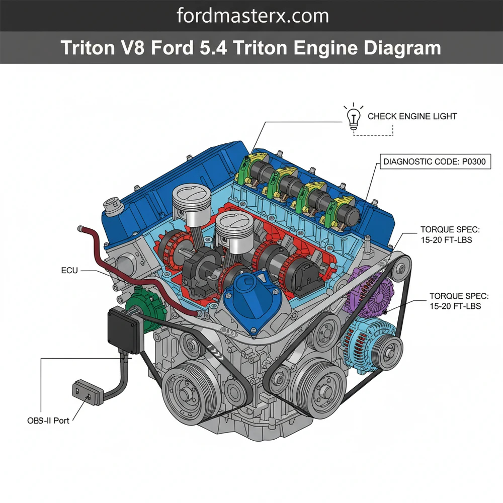
Below is a conceptual representation of the major components typically found in a 5.4 Triton engine diagram:
[DIAGRAM_PLACEHOLDER: A detailed exploded view of a Ford 5.4L Triton V8 showing the intake manifold, timing chain assembly, accessory belt routing, and sensor locations including ECU inputs and OBD-II interface points.]
Step-By-Step Guide: Reading and Applying the Engine Diagram

Interpreting a triton v8 ford 5.4 triton engine diagram can be overwhelming at first glance due to the density of components. However, by following a systematic approach, you can use the diagram to perform complex tasks like replacing a timing chain or diagnosing a stubborn check engine light. Follow these steps to master the use of your engine diagram.
Step 1: Orient Your Perspective
Before you touch a tool, align yourself with the diagram. Most automotive diagrams are drawn from the perspective of standing in front of the vehicle looking toward the firewall. Identify the “Front of Engine” marker on the diagram. This will help you distinguish between Bank 1 (passenger side on RHD vehicles) and Bank 2 (driver side), which is critical when identifying which cylinder is throwing a specific diagnostic code.
Step 2: Trace the Accessory Belt Routing
One of the most common uses for an engine diagram is re-installing the accessory belt. Locate the crankshaft pulley (the largest pulley at the bottom) and follow the line of the belt through the tensioner and idler pulleys. Using the diagram to ensure the “ribbed” side and “smooth” side of the belt touch the correct pulleys is essential to prevent premature belt failure or reversed component rotation.
Step 3: Map the Coolant Flow
The 5.4 Triton has a specific coolant flow path that must be understood to prevent overheating. Use the diagram to identify the water pump location and the thermostat housing. Following the coolant flow helps you identify potential air pockets in the system or determine if a heater core bypass is necessary. This is especially important when flushing the system or replacing the radiator hoses.
Step 4: Locate the Timing Chain Components
The timing chain system is the heart of the 5.4L V8. The diagram will show the relationship between the crankshaft sprocket and the two camshaft sprockets. On 3-valve models, look for the VCT (Variable Cam Timing) solenoids. Reading the diagram carefully will show the “timing marks” or colored links on the chain that must align perfectly with the dots on the sprockets to ensure the engine is in time.
The 5.4L Triton is an interference engine. If the timing chain is improperly installed based on a misunderstood diagram, the pistons can strike the valves, leading to catastrophic engine failure. Always double-check your alignment marks before rotating the engine.
Step 5: Identify ECU and Sensor Connections
When a check engine light appears, your OBD-II scanner will provide a code. Use the engine diagram to find the physical location of the sensor associated with that code. For example, if you receive a code for a “Bank 2 Sensor 1” O2 sensor, the diagram will show you exactly which side of the exhaust manifold to inspect. This prevents the common mistake of replacing the wrong part.
Step 6: Reference Torque Specs and Bolt Sequences
A comprehensive diagram often includes or links to a table of torque specs. For the 5.4L Triton, specific sequences are required for tightening intake manifold bolts and cylinder head bolts. Use the numbered sequence on the diagram to tighten fasteners from the center outward to ensure an even seal and prevent warping of the components.
Common Issues and Troubleshooting with the Diagram

The 5.4L Triton engine is known for a few specific mechanical quirks that the triton v8 ford 5.4 triton engine diagram can help you solve. One of the most frequent issues is the “ticking” or “clattering” sound often associated with the timing chain tensioners or cam phasers. By using the diagram to identify the location of these components, you can use a mechanic’s stethoscope to pin-point the source of the noise before tearing the engine down.
Another common problem involves the ignition system. If you experience a misfire but the check engine light hasn’t flashed a specific cylinder code yet, the diagram can help you trace the wiring harness back to the ECU. Often, what looks like a failed coil-on-plug is actually a frayed wire or a loose connection at the main harness block. Furthermore, the diagram is essential for troubleshooting vacuum leaks. The 5.4L has several vacuum lines tucked behind the intake manifold that are nearly impossible to see without a visual guide, yet they are a primary cause of lean-condition diagnostic codes.
Pro Tips and Best Maintenance Practices
To keep your 5.4L Triton V8 running for hundreds of thousands of miles, professional mechanics recommend several best practices that go beyond the basic diagram information. Efficiency and longevity are the goals here.
When replacing spark plugs on a 3-valve 5.4L, always use a dedicated spark plug socket and apply a small amount of nickel anti-seize to the ground shield (not the threads). Reference your diagram for the exact cylinder layout to ensure you don’t cross-thread the difficult-to-reach rear plugs.
- ✓ Oil Quality: Always use the manufacturer-recommended oil weight (usually 5W-20). The VCT system relies on hydraulic pressure to operate the timing chain phasers; thick or dirty oil will lead to premature timing failure.
- ✓ OBD-II Scanning: Keep a basic OBD-II scanner in your glovebox. When the check engine light illuminates, you can immediately identify the code and use your diagram to find the culprit sensor.
- ✓ Coolant Maintenance: Follow the coolant flow diagram to ensure no air is trapped in the heater core. Air pockets can cause localized hot spots in the cylinder heads, leading to cracked manifolds or blown gaskets.
- ✓ Torque Accuracy: Never guess on a torque spec. Whether it’s the 11 lb-ft for the valve covers or the high-torque requirements of the harmonic balancer, precision is the key to preventing oil leaks and vibration.
In conclusion, the triton v8 ford 5.4 triton engine diagram is the most valuable tool in your arsenal. By understanding the accessory belt layout, the timing chain synchronization, and the various sensor locations, you can take control of your vehicle’s maintenance. Regular attention to the cooling system and oil pressure, guided by an accurate diagram, will ensure that your Ford truck remains a reliable partner on the road for years to come. Whenever you face a complex diagnostic code or a mystery noise, return to the diagram—it usually holds the answer.
Step-by-Step Guide to Understanding the Triton V8 Ford 5.4 Triton Engine Diagram: Complete Guide
Identify the main engine block and cylinder head configuration within the diagram to establish a baseline.
Locate the specific component you need to service, such as the fuel rail or ignition coils.
Understand how the wiring harness connects sensors to the ECU for proper data transmission.
Apply the correct torque spec to all bolts during reassembly to ensure structural integrity.
Verify that all vacuum lines and electrical connectors match the diagram routing to avoid errors.
Complete the process by using an OBD-II scanner to clear any check engine light or diagnostic code.
Frequently Asked Questions
Where is the ECU located?
The ECU on most Ford trucks with the 5.4 Triton engine is located on the passenger side firewall inside the engine compartment. It is secured by several bolts and connected to the main wiring harness. This central module processes data from various sensors to manage engine performance and fuel efficiency.
What does the engine diagram show?
This Triton V8 Ford 5.4 Triton engine diagram displays the spatial relationship between internal and external components. It highlights the intake manifold, cylinder heads, accessory drive belt routing, and sensor locations, allowing mechanics to visualize how the modular engine architecture fits together for faster diagnostics and more accurate repairs.
How many spark plug connections does this engine have?
The 5.4 Triton V8 features eight spark plug connections, one for each cylinder. Depending on the specific year, these utilize a coil-on-plug design where an individual ignition coil sits directly atop each plug. These coils are controlled by the ECU to ensure precise timing during the combustion cycle.
What are the symptoms of a bad cam phaser?
Common symptoms include a persistent ticking or knocking sound, especially at idle, and a triggered check engine light. You may also experience rough idling or reduced engine power. Using an OBD-II scanner will often reveal a specific diagnostic code related to camshaft timing or over-retarded performance issues.
Can I replace the spark plugs myself?
Yes, you can replace spark plugs yourself, but caution is required due to the 5.4 Triton engine history of seized or broken plugs. Using the correct tools and a specific removal procedure is vital. Always apply the manufacturer-recommended torque spec during installation to prevent future cylinder head damage.
What tools do I need for timing chain repair?
To repair the timing system, you need a comprehensive socket set, a torque wrench, cam phaser locking tools, and a crankshaft positioning tool. Because this is an interference engine, precise alignment is mandatory to prevent valves from hitting pistons, making specialized alignment and locking tools absolutely necessary.


