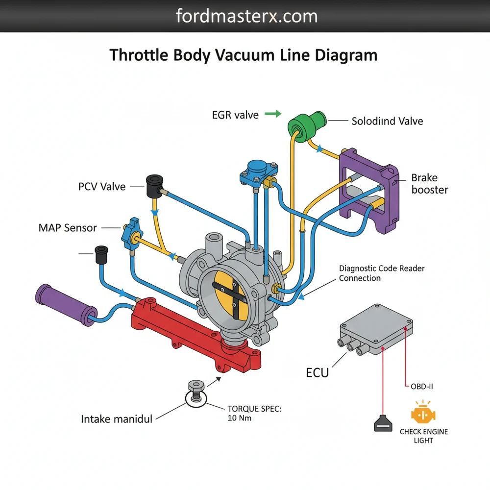
Throttle Body Vacuum Line Diagram: Easy Routing Guide
A throttle body vacuum line diagram illustrates the specific routing of hoses connecting the throttle body to components like the MAP sensor, EVAP canister, and fuel pressure regulator. It ensures that the ECU receives correct air pressure readings, preventing issues like a rough idle, surging, or a triggered check engine light.
📌 Key Takeaways
- Visualizes the airflow path between the intake and various engine sensors
- The throttle body acts as the central hub for vacuum distribution
- Vacuum leaks lead to lean fuel mixtures and poor engine performance
- Always use high-quality, heat-resistant hoses that meet OEM standards
- Essential for troubleshooting idling issues or emissions-related failures
The throttle body is often described as the lungs of an internal combustion engine, controlling the amount of air that enters the intake manifold. However, it does much more than just house a butterfly valve. For DIY enthusiasts working on vehicles from the 1980s through the early 2010s, understanding the maze of thin rubber tubes connected to the throttle body is crucial. These are vacuum lines, and they act as a pneumatic signaling system that controls everything from your idle speed to your power brakes and emissions systems. A throttle body vacuum line diagram is the essential roadmap required to ensure these lines are routed correctly, as a single misplaced hose can lead to a host of engine performance issues, including surging idles, poor fuel economy, and failed emissions tests.
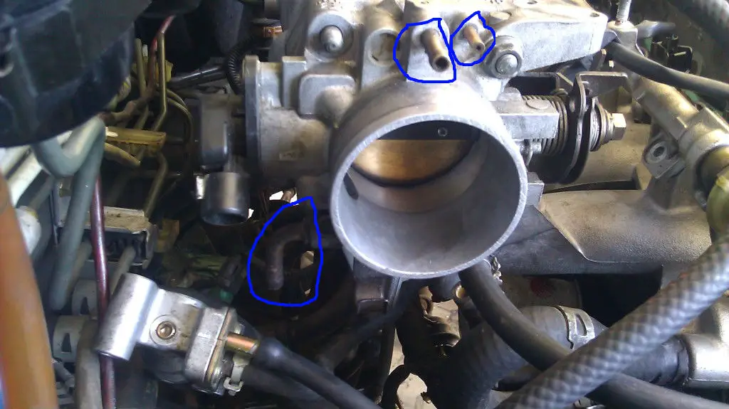
When you look at a throttle body, you will see several small brass or plastic nipples protruding from its housing. These ports are strategically placed either before or after the throttle plate to provide specific types of vacuum signals. Understanding where these lines go—and why they go there—is the difference between a smooth-running engine and a frustrating “Check Engine” light. This guide will break down the complexities of vacuum routing, providing you with the practical knowledge to diagnose, repair, and replace your vacuum system with confidence.
Main Components and Features of the Vacuum System
To read a diagram effectively, you must first identify the primary players in the vacuum circuit. While every vehicle manufacturer (OEM) has a slightly different layout, the following components are almost universally connected to the throttle body vacuum system:
- The Throttle Body Ports: Most throttle bodies feature two types of vacuum:
- Manifold Vacuum: Taken from behind the throttle plate. This vacuum is strongest when the throttle is closed (at idle).
- Ported Vacuum: Taken from just in front of or right at the edge of the throttle plate. This signal only becomes strong once the throttle begins to open.
- MAP Sensor (Manifold Absolute Pressure): Often connected via a 1/4″ or 3/16″ vacuum line, this sensor tells the ECU how much load is on the engine. Wire colors for these sensors often include a 5V reference (usually Gray or Blue), a ground (Black/Green), and a signal wire (often Green or Red).
- PCV Valve (Positive Crankcase Ventilation): Usually the thickest vacuum line (often 3/8″ or 1/2″ ID). It draws oil vapors from the crankcase back into the intake to be burned.
- EVAP Purge Solenoid: This component manages the flow of fuel vapors from the charcoal canister. It is typically connected to a ported vacuum source so that vapors are only burned while the vehicle is cruising, not at idle.
- Fuel Pressure Regulator (FPR): On older fuel-injected vehicles, a small vacuum line connects the throttle body to the FPR. It adjusts fuel pressure based on engine load.
- Brake Booster: While usually connected to the manifold itself, some systems route the large vacuum supply through a dedicated port on the throttle body assembly to assist in power braking.
How to Use and Read a Vacuum Line Diagram

Reading a vacuum diagram can feel like looking at a plate of spaghetti. However, manufacturers use specific conventions to make them readable. Most DIYers will find these diagrams on a “Vehicle Emission Control Information” (VECI) sticker located on the underside of the hood or on the radiator shroud. If that sticker is missing, a factory service manual is your next best source.
When studying the diagram, look for the central rectangular or circular shape representing the throttle body. Lines emanating from this shape represent the hoses. Solid lines typically indicate rubber vacuum hoses, while dashed or colored lines might indicate plastic hard-lines or specific sub-systems like the EGR (Exhaust Gas Recirculation) circuit.
Pay close attention to “T-junctions” and “Check Valves.” A T-junction is indicated by a simple intersecting line with a dot, showing where one vacuum source is shared by two components. A check valve is usually represented by a small circle or a triangle within the line; this indicates that air can only flow in one direction. If you install a check valve backward, the component it feeds (like the power brakes or HVAC doors) will fail to operate. Some diagrams also use letter codes near the throttle body ports—for example, “P” for Purge, “E” for EGR, and “R” for Regulator. Always match the letter on the diagram to the letter stamped into the metal of the throttle body casting.
Tips for Working with Vacuum Lines
Replacing or rerouting vacuum lines is a common maintenance task, especially as heat and age make rubber hoses brittle and prone to cracking. Here are some practical tips for a successful job:
- One at a Time: Never pull all the vacuum lines off at once. Replace them one by one. If you must remove multiple lines, use color-coded electrical tape or numbered stickers to label both the hose and the port it came from.
- Upgrade to Silicone: Standard EPDM rubber hoses eventually dry out and crack. High-quality silicone vacuum tubing is more expensive but resists heat much better and remains flexible for decades. It is an excellent upgrade for turbocharged engines where under-hood temperatures are extreme.
- Use Proper Tools: Removing an old, stuck hose can snap a plastic vacuum nipple. Use a specialized hose removal pick or a pair of long-nose pliers to gently twist the hose until the seal breaks before pulling it off.
- Check for “Soft” Spots: Sometimes a vacuum line looks fine on the outside but has collapsed internally or become “mushy” due to oil exposure. Squeeze the lines; they should feel firm and consistent throughout their length.
Troubleshooting Common Vacuum Issues
Vacuum leaks are the most common cause of “unsolvable” engine problems. Because the engine is drawing in “unmetered air” (air the computer doesn’t know about), the air-fuel ratio becomes lean. This causes the computer to compensate by dumping more fuel, often resulting in a rough idle and a “System Too Lean” (P0171/P0174) diagnostic code.
The Visual and Audio Inspection: With the engine running, listen for a distinct “hissing” sound around the throttle body. You can often pinpoint a leak by using a length of garden hose as a stethoscope; hold one end to your ear and move the other end around the vacuum ports.
The Soapy Water or Smoke Test: For hard-to-find leaks, a smoke machine is the professional’s choice. By pumping thick, non-toxic smoke into the intake manifold, you can see exactly where it escapes. For a low-budget DIY method, spraying a small amount of soapy water on the lines while the engine is running (or under light pressure) can reveal bubbles. Note: Avoid spraying flammable carb cleaners on a hot engine, as this poses a significant fire risk.
Using a Vacuum Gauge: A manual vacuum gauge is one of the most underrated tools in a DIYer’s kit. Connect it to a manifold vacuum port on the throttle body. At idle, a healthy engine should show a steady needle between 17 and 21 in-Hg (inches of mercury). A vibrating needle often indicates worn valve guides, while a low, steady reading might indicate late ignition timing or a major leak in the main intake gasket.
In conclusion, while the network of tubes surrounding your throttle body may look intimidating, it follows a logical path dictated by the physics of engine suction. By using an accurate throttle body vacuum line diagram, identifying your components, and using the right materials, you can maintain your engine’s efficiency and performance. Whether you are chasing an elusive rough idle or restoring a classic fuel-injected engine, mastering the vacuum system is a fundamental skill for any serious home mechanic.
Step-by-Step Guide to Understanding the Throttle Body Vacuum Line Diagram: Easy Routing Guide
Identify the throttle body assembly located between the air filter box and the intake manifold.
Locate the individual vacuum ports on the throttle body housing by comparing them to your diagram.
Understand how each hose routes to its corresponding sensor or actuator to avoid crossed connections.
Connect the new vacuum hoses securely to each port, ensuring they are seated firmly without kinks.
Verify that all connections match the diagram and that no ports are left open or leaking.
Complete the process by starting the engine to check for a steady idle and no error codes.
Frequently Asked Questions
Where is the throttle body vacuum line located?
Vacuum lines are typically found attached to small ports on the side or rear of the throttle body housing. They connect this central air valve to various engine sensors and emissions components. You can usually find them between the air intake boot and the intake manifold plenum on top of the engine.
What does a throttle body vacuum line diagram show?
This diagram illustrates the specific paths and connection points for all vacuum-operated hoses originating at the throttle body. It helps identify which port leads to the EVAP purge valve, the fuel pressure regulator, and other critical vacuum-actuated systems required by the ECU for proper engine management and performance.
How many connections does a throttle body have?
Most modern throttle bodies have between two and five vacuum connections, depending on the vehicle’s emissions system. These ports allow the engine to monitor manifold pressure and manage vapor recovery. Always refer to your specific diagram to ensure every port is either connected or properly capped to prevent vacuum leaks.
What are the symptoms of a bad vacuum line?
A leaking or disconnected vacuum line often triggers a check engine light and a lean diagnostic code. You may experience a rough or high idle, poor acceleration, or whistling sounds from the engine bay. Using an OBD-II scanner can help confirm if a vacuum leak is affecting the fuel trim.
Can I replace these vacuum lines myself?
Yes, replacing vacuum lines is a straightforward DIY task that requires minimal tools. By following a throttle body vacuum line diagram, you can swap out brittle or cracked hoses one at a time to ensure correct routing. This simple maintenance task can significantly improve engine stability and overall fuel economy.
What tools do I need for this task?
You will primarily need needle-nose pliers to release spring clamps and a utility knife to trim new hoses to length. A torque spec wrench may be necessary if you must remove the throttle body itself. Additionally, an OBD-II scanner is helpful for clearing any persistent error codes after the repair.